Advertisement
Quick Links
INSTRUCTION MANUAL
BEFORE USE ....
Thank you for choosing us. Before use, please check con-
tents of the package you received as outlined below.
If you have any problems or questions with the product,
please contact our sales office or representatives.
■ PACKAGE INCLUDES:
Signal conditioner
(body + base socket + input resistor)..................................(1)
Input resistor is provided only with current input type.
■ MODEL NO.
Confirm Model No. marking on the product to be exactly
what you ordered.
■ INSTRUCTION MANUAL
This manual describes necessary points of caution when
you use this product, including installation, connection and
basic maintenance procedures.
POINTS OF CAUTION
■ POWER INPUT RATING & OPERATIONAL RANGE
• Locate the power input rating marked on the product and
confirm its operational range as indicated below:
85 – 264V AC rating: 85 – 264V, 47 – 66 Hz, approx. 4 – 6VA
11 – 27V DC rating: 11 – 27V, approx. 3W
■ GENERAL PRECAUTIONS
• Before you remove the unit from its base socket or mount
it, turn off the power supply and input signal for safety.
■ ENVIRONMENT
• Indoor use.
• When heavy dust or metal particles are present in the
air, install the unit inside proper housing with sufficient
ventilation.
• Do not install the unit where it is subjected to continuous
vibration. Do not subject the unit to physical impact.
• Environmental temperature must be within -5 to +55°C
(23 to 131°F) with relative humidity within 30 to 90% RH
in order to ensure adequate life span and operation.
• Be sure that the ventilation slits are not covered with ca-
bles, etc.
■ WIRING
• Do not install cables close to noise sources (relay drive
cable, high frequency line, etc.).
• Do not bind these cables together with those in which
noises are present. Do not install them in the same duct.
MG CO., LTD. www.mgco.jp
5-2-55 Minamitsumori, Nishinari-ku, Osaka 557-0063 JAPAN
ISOLATOR
MODEL
■ AND ....
• The unit is designed to function as soon as power is sup-
plied, however, a warm up for 10 minutes is required for
satisfying complete performance described in the data
sheet.
• With voltage output, do not leave the output terminals
shortcircuited for a long time. The unit is designed to
endure it without breakdown, however, it may shorten ap-
propriate life duration.
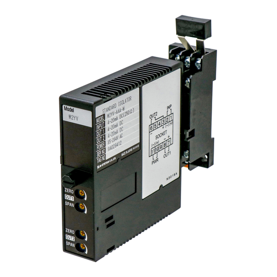
COMPONENT IDENTIFICATION
Body
Fixing Screw
Zero Adj.
Output 1
Span Adj.
Zero Adj.
Output 2*
Span Adj.
*Provided only for dual output.
INSTALLATION
Loosen the fixing screw at the front of the unit in order to
separate the body from the base socket.
■ DIN RAIL MOUNTING
Set the base socket so that
its DIN rail adaptor is at
the bottom. Hang the up-
per hook at the rear side
of base socket on the DIN
rail and push in the lower.
When removing the socket,
push down the DIN rail
adaptor utilizing a minus
screwdriver and pull.
■ WALL MOUNTING
Refer to "EXTERNAL DIMENSIONS."
W2YV
Base Socket
Input Resistor
Connection
Diagram
Specifications
DIN Rail
35mm wide
Spring Loaded
DIN Rail Adaptor
EM-5520 Rev.5 P. 1 / 3
Advertisement

Related Manuals for MG W2YV


Summary of Contents for MG W2YV
- Page 1 • Do not bind these cables together with those in which noises are present. Do not install them in the same duct. EM-5520 Rev.5 P. 1 / 3 MG CO., LTD. www.mgco.jp 5-2-55 Minamitsumori, Nishinari-ku, Osaka 557-0063 JAPAN...
- Page 2 The section enclosed by broken line is only with 2nd output option. *Input shunt resistor attached for current input. Input shunt resistor attached for current input. EM-5520 Rev.5 P. 2 / 3 MG CO., LTD. www.mgco.jp 5-2-55 Minamitsumori, Nishinari-ku, Osaka 557-0063 JAPAN...
- Page 3 4) When ZERO value is changed, repeat the above proce- dure 1) – 3). 5) Go through the same procedure for the Output 2. EM-5520 Rev.5 P. 3 / 3 MG CO., LTD. www.mgco.jp 5-2-55 Minamitsumori, Nishinari-ku, Osaka 557-0063 JAPAN...
Need help?
Do you have a question about the W2YV and is the answer not in the manual?
Questions and answers