Table of Contents
Advertisement
Quick Links
Advertisement
Table of Contents

Summary of Contents for Mersen MULTIVERT I-XTENSIO
- Page 1 MULTIVERT® MART ODULE FOR TENSIO ODBUS VERSION FOR NERGY MONITORING IEC FUSE SWITCH DISCONNECTORS S ER MA N U A L MPROVING SERVICE EFFICIENCY OF OLTAGE ETWORKS EP.MERSEN.COM V3-20240404 - User manual – Smart Module...
-
Page 2: Table Of Contents
9 . MODBUS PA RA METERS ................... 26 10 . MODBUS MEA SUREMENT PROVIDED ............27 11. TROUBLE SHOOTING ..................28 12. CYBER SECURITY .................... 29 13. A PPENDIX ......................30 EP.MERSEN.COM V3-20240404 - User manual – Smart Module 2/31... -
Page 3: Document
USER MANUAL Smart Module for MULTIVERT® i-Xtensio 1. DOCUMENT All documentation on our SMART Module RTU is available on the MERSEN website EP.MERSEN.COM Additional instruction manuals • Datasheet • Mounting instruction / Legal notice Configuration Software (on request) • Software for firmware upgrade (on request) •... -
Page 4: Hazards And Warnings
2. HAZARDS AND WARNINGS The assembly, use, servicing and maintenance of this equipment must only be carried out by trained, qualified professionals. MERSEN shall not be held responsible for failure to comply with the instructions in this manual. 2.1 Risk of electrocution, burns... -
Page 5: Preliminary Operations
Before commissioning your SMART module, make sure it operates under the latest firmware versions. The latest firmware versions are available on the MERSEN website. The firmware upgrade is done using the “SmartModbusModuleSoftwareSetup” software, by connecting a laptop to your SMART module. Have a look on the description done in the further chapter. -
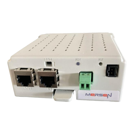
Page 6: Product Overview
USER MANUAL Smart Module for MULTIVERT® i-Xtensio 5. PRODUCT OVERVIEW 5.1 Overview of ProGrid equipped with Smart Module and sensor devices Example of Multivert i-Xtensio pôle switching overview with Smart Module solution 5.2 Overview of Smart Module – Modbus RTU version EP.MERSEN.COM... - Page 7 → LED becomes orange with these 2 actions. Digital Outputs connections Digital outputs to get alarm on fuse blown and temperature max thresholds / Normally opened Dip Switch • Allow presetting of slave address • Activate termination resistance EP.MERSEN.COM V3-20240404 - User manual – Smart Module 7/31...
- Page 8 5.4 Engineering Software installation The module is delivered with a software to test, calibrate and set some parameters of the Smart Module using a laptop. Once you got the last updated software under Mersen website, you should : → Unzip the file “SmartModbusModuleSoftwareSetup_X.X.XX_x64”...
- Page 9 “Refresh” button. If the connection is completed it is shown by the “Connected” button If there is an issue of the connection, a message will appear, you must check the module connection EP.MERSEN.COM V3-20240404 - User manual – Smart Module 9/31...
- Page 10 → Firmware version: coming from the module directly to follow the firmware versioning → Upload new firmware version: press “Start update”, “Open” the new firmware version and “update” the firmware (file.bin) EP.MERSEN.COM V3-20240404 - User manual – Smart Module 10/31...
- Page 11 USER MANUAL Smart Module for MULTIVERT® i-Xtensio → Before to change the page, don’t forget to “Apply” your changes → otherwise, you will get an Error message EP.MERSEN.COM V3-20240404 - User manual – Smart Module 11/31...
- Page 12 On this page you have several subchapters to adjust the settings of the module and the Modbus communication This configuration tab is used to display “read” and to adjust “write”, if needed, the different values available in the Smart Module EP.MERSEN.COM V3-20240404 - User manual – Smart Module 12/31...
- Page 13 → Time duration for means: could be modified by the customer → Active power calculated on 2 possibilities : “Wideband” or “Fundamental”, could be modified by the customer → Frequency: 50Hz or 60Hz, could be modified by the customer EP.MERSEN.COM V3-20240404 - User manual – Smart Module 13/31...
- Page 14 → Parity: Even as preset value, could be modified by the customer Several possibilities : none / even / odd 5.5.3.3 CT phase visualization → CT ratio: confirmation of the selection done on Main page of Current transformer EP.MERSEN.COM V3-20240404 - User manual – Smart Module 14/31...
- Page 15 → Voltage nominal value U : could be modified by the customer? → Current hysteresis value : could be modified by the customer? → Voltage hysteresis value : could be modified by the customer? EP.MERSEN.COM V3-20240404 - User manual – Smart Module 15/31...
- Page 16 → Minimum time message: time minimum to get a message, could be modified by the customer → Modbus Waiting time before answer : time to wait for having an answer from the module , could be modified by the customer EP.MERSEN.COM V3-20240404 - User manual – Smart Module 16/31...
- Page 17 On this page you have several subchapters to visualize the measured or calculated values → Time and date of means values: date and time of the last mean calculation → Temperature Measurement: value of the temperature EP.MERSEN.COM V3-20240404 - User manual – Smart Module 17/31...
- Page 18 → Current mean: mean calculated on current values for each phase → Current min: current value min found during current mean calculation → Current max: current value max found during current mean calculation → Cosphi : cosphi calculated EP.MERSEN.COM V3-20240404 - User manual – Smart Module 18/31...
- Page 19 → Reactive power mean: reactive power calculated on active power values → Reactive power min: reactive power value min found during reactive power mean calculation → Reactive power max: reactive power value max found during reactive power mean calculation EP.MERSEN.COM V3-20240404 - User manual – Smart Module 19/31...
- Page 20 • Red : gap of voltage measurements per phase : Fuse blow or Fusegear opened → Temperature status: • Green : no issue, temperature below the temperature threshold • Red : temperature over the temperature threshold EP.MERSEN.COM V3-20240404 - User manual – Smart Module 20/31...
-
Page 21: Terminal Connections
1,5 mm2 ~ Ø 1,3mm,690V Brown L1 voltage input 1,5 mm2 ~ Ø 1,3mm,690V Yellow Voltage measurement inputs connections BACK Voltage Measurement Fuse control inputs Neutral Current measurements inputs input Current measurement inputs connections EP.MERSEN.COM V3-20240404 - User manual – Smart Module 21/31... - Page 22 2 = GND (or 0V) 3 = Not connected 4 = D1 (A) 5 = D0 (B) 6 = 24V 7 = 24V 8 = GND ADDR Dip switch 1234 position EP.MERSEN.COM V3-20240404 - User manual – Smart Module 22/31...
- Page 23 1 / top 0 / bottom EP.MERSEN.COM V3-20240404 - User manual – Smart Module 23/31...
- Page 24 Using the dip switch you should put it at position 1, regardless of other positions of the dip switch pins. The delivery position is always at 0. position 1 / top 0 / bottom Termination resistance position at 1 position 1 / top 0 / bottom EP.MERSEN.COM V3-20240404 - User manual – Smart Module 24/31...
-
Page 25: Power Direction Setting
• Change current transformer side of installation as shown on the upper pictures • Or reverse the connection of the module as shown below N 6 5 4 3 2 1 N EP.MERSEN.COM V3-20240404 - User manual – Smart Module 25/31... -
Page 26: Technical Data
Max. Bus participants up to 247 1200 – 115200 b/s (default = 57kb/s) Transmission speed Mounting Horizontal Mechanical Housing Classification V-2 according to UL 94 characteristics Dimensions HxWxD 39,5x95x102 mm Weight 200 g EP.MERSEN.COM V3-20240404 - User manual – Smart Module 26/31... -
Page 27: Modbus Parameters
50536 HR ADDR_FCT_PRIVATE_APP_DATA8 UINT16 0 to 65535 firmware data //Temperature //Threshold 50573 HR ADDR_FCT_PRIVATE_TEMP_THRESHOLD °C INT16 60 to 90 90 threshold temperature value *Excel file of Modbus communication table available on request EP.MERSEN.COM V3-20240404 - User manual – Smart Module 27/31... -
Page 28: Modbus Measurement Provided
//Temperature alert 1 > threshold temperature value ADDR_FCT_PRIVATE_TEMP_ALERT 50574 0 < threshold temperature value // Temperature measurement 50575 ADDR_FCT_PRIVATE_TEMP_MEASUREMENT °C float32 temperature value *Excel file of Modbus communication table available on request EP.MERSEN.COM V3-20240404 - User manual – Smart Module 28/31... -
Page 29: Trouble Shooting
Failure of the module connection Check connector position at the back of the module Voltage data partially Failure of the module connection Check connector position shown at the back of the module EP.MERSEN.COM V3-20240404 - User manual – Smart Module 29/31... -
Page 30: Cyber Security
MERSEN and its affiliates are not liable for damage and/or losses related to such security breaches, unauthorized access, interference, intrusion, leakage and/or theft of data or information. -
Page 31: A Ppendix
Fail safe Modbus connections – RJ45 According to Modbus specification “Modbus over serial line” - Pin 4 : B (D-) - Pin 5 : A (D+) - Pin 8 : Gnd. EP.MERSEN.COM V3-20240404 - User manual – Smart Module 31/31... - Page 32 USER MANUAL Smart Module for MULTIVERT® i-Xtensio CONTACT US MERSEN FRANCE SB SAS 15 Rue Jacques Vaucanson 69720 Saint Bonnet-de-Mure France T +33(0)4 72 22 6611 @ TS.SBM@mersen.com EP.MERSEN.COM V3-20240404 - User manual – Smart Module 32/31...
Need help?
Do you have a question about the MULTIVERT I-XTENSIO and is the answer not in the manual?
Questions and answers