
Summary of Contents for Makermade cnc500
- Page 1 ASSEMBLY GUIDE Bring Your Ideas To Life With The MakerMade cnc500 | 2023 ©MAKERMADE, LLC...
-
Page 2: Safety Warnings
Safety Warnings: During set up, please make sure the machine is on a solid surface. In case of emergency, press the emergency stop button quickly. Wear safety glasses when operating the machine. Please use a brush to remove debris, do not blow on the machine. -
Page 3: Table Of Contents
Section 01.1: Tools you need Step 12: Test Section 01.2: Machine overview Step 13: Installation of router bit to Section 02: Assembling the cnc500 ER-11 Collet Step 01: Frame Installation Step 14: Clamping workpiece Step 02: Attaching Rubber Feet... -
Page 4: Section 01: What's In The Box
What’s in S E C T I O N the Box? HARDWARE BAG 1 M5*20 4PCS BASE FRAME HARDWARE BAG 2 M5*20 16PCS WASTEBOARD FIXED HARDWARE BAG 3 M5*20 4PCS BASE FEET SCREWS HARDWARE BAG 4 M5*20 4PCS Z AXIS MOUNT HARDWARE BAG 5 M5*7 4PCS 775 MOTOR CLAMP HARDWARE BAG 6... -
Page 5: Components
Components: Left Y-Axis Shield*1 Density Plate*2 Right Y-Axis Assembly*1 Z-Axis assembly 2020 Rear Crossmember*1 Left Y-Axis Assembly*1 2020 Rear Crossmember*1 2020 Bottom Crossmember*2 ESP32 Control Box + Drag C1hain*1 2040 Bottom Crossbeam*1 cnc500 Product Manual... - Page 6 ESP32 Control Box*1 TS35 Touch Screen Kit*1 775 Spindle Motor*1 775 Motor Chuck*1 ER-11 6mm Collet *1 Motor Mounting Bracket*1 Coupling*1 Rubber Foot Pad*4 Mainboard Fixing Piece*2 Fixture*6 Drag Chain Support X-Axis Limit Trigger Plate*2...
-
Page 7: Section 01.1: Tools You Need
Tools S E C T I O N 01.1 you need Scissor File Oblique Flier One-way Screwdriver Safety Goggles Open-end Wrench Hexagonal Wrench cnc500 Product Manual... -
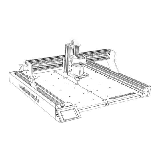
Page 8: Section 01.2: Machine Overview
Machine S E C T I O N 01.2 Overview Z-Axis Motor T8-4 Screw 775 Spindle Motor 4080U Side Profile Emergency Stop Switch DC Power Interface USB Interface TF Card Slot Engraving Platform TS35 Touch Screen Power Switch... - Page 9 Limit Switch Drag Chain X-Axis Motor Y-Axis Motor Rubber Feet cnc500 Product Manual...
-
Page 10: Section 02: Assembling The Cnc500
Assembling S E C T I O N the cnc500 Step 01: FRAME INSTALLATION Make sure holes with notches are facing out on each side extrusion. Use 4mm Allen wrench to attach four base frame screws. REQUIRED PARTS: • 4 pcs -Base frame screws •... - Page 11 ATTACH RUBBER FEET Attach two rubber feet to bottom of each side assembly TO SIDE ASSEMBLIES using M5x20 screws REQUIRED PARTS: • 4 pcs - Rubber feet • 4 pcs - M5x20 screws • 2 Side Assemblies cnc500 Product Manual...
- Page 12 Step 03: ATTACH BOTTOM FRAME TO SIDE ASSEMBLIES When the frame is installed with the profile plane facing upwards, pay attention to the direction of the left side 2020 profile. REQUIRED PARTS: • 4 pcs -M5x48 side fixed base frame screws •...
-
Page 13: Step 04: Waste Board Installation
WASTE BOARD INSTALLATION With the surface of the density plate facing upward, screw 20 screws through the density plate into the profile. REQUIRED PARTS: • 16 pcs -M5 x 20 screws • 2 pcs - Waste Board cnc500 Product Manual... -
Page 14: Step 05: X-Axis Motor Installation
Step 05: X-AXIS MOTOR INSTALLATION Attach stepper motor to Attach coupling to stepper motor Left Y-Axis assembly shaft with set screws. One set screw should go on flat side of shaft REQUIRED PARTS: • 1 pcs - X-Axis stepper motor •... -
Page 15: Step 06: X-Axis Installation
Use four M5 X 12 screws to attach the X-Axis Note the orientation of the X-Axis with the nut end facing up to the Right Y-Axis assembly REQUIRED PARTS: • 4 pcs -M5X12 screws • X-Axis Assembly • 3mm wrench cnc500 Product Manual... -
Page 16: Step 07: X-Axis Installation
Step 07: X-AXIS INSTALLATION CONTINUED From the back of the machine push the X-axis carriage to the left so the lead screw goes through the bearing hole on the right Y-axis assembly Manually turn the left Y-axis lead screw to align left and right Y-axis REQUIRED PARTS: •... - Page 17 X-axis profile. From the back of the machine push the X-axis carriage to the right, insert the lead screw into the coupling and tighten the two set screws on the coupling cnc500 Product Manual...
-
Page 18: Step 08: Z-Axis Installation
Step 08: Z-AXIS INSTALLATION Use 2 mm Allen wrench to loosen the two set screws on the coupling Move the carriage down to find the top two holes to attach the assembly Use 4 mm Allen wrench to attach assembly using two M5X20 screws. - Page 19 Use 4 mm Allen wrench to secure assembly using two M5X20 screws. Tighten the screws Insert the lead screw back into the coupling and tighten up the two set screws cnc500 Product Manual...
-
Page 20: Step 09: Drag Chain Installation
Step 09: DRAG CHAIN INSTALLATION REQUIRED PARTS: • 4 pcs -M4X6 screws • Upper drag chain bracket • Lower drag chain bracket • 2.5 mm allen wrench • 2 mm allen wrench... - Page 21 T-nut. -M3X5 Screws*2 -M5X6 Screws*2 Insert it into the profile slot and tighten it -T-Nut 20-M5*2 slightly. Lock M3X5 screw first, and then -Mainboard Fixing Piece*2 tighten M5X6 screw. -2.0 Hexagonal Wrench -3.0 Hexagonal Wrench cnc500 Product Manual...
-
Page 22: Step 11: Installing The Millie
Step 11: REQUIRED PARTS: Z-Axis Motor Cable INSTALLING THE MILLIE X-Axis Limit Switch Cable Attach the motor mount Attach the motor to the Attach the chuck with to the Z-Axis assembly motor mount using the ER-11 collet to the spindle using the (4) M5X6 (2) M4X6 screws. -
Page 23: Step 11.1: Installation Of Cables From Harness
INSTALLATION OF CABLES FROM HARNESS Plug in the Z-axis motor cable and X-axis limit switch cable. Plug in the 775 motor cable (Optional) REQUIRED PARTS: Z-Axis Motor Cable X-Axis Limit Switch Cable OPTIONAL PARTS: 775 Motor 775 Motor Cable cnc500 Product Manual... -
Page 24: Step 12: Test
Step 12: TEST Make sure the emergency stop switch is popped up by lightly twisting it to the right, then plug in the power and press the metal power switch. The green light will turn on. If the screen lights up, the touch screen is functioning properly. -
Page 25: Step 13: Installation Of Router Bit To
Insert the collet into the nut. Insert the bit into the collet/nut assembly. Presss the shaft lock in (located on the side of the shaft) and tighen collet nut. cnc500 Product Manual... -
Page 26: Step 14: Clamping Workpiece
Step 14: CLAMPING WORKPIECE Use Two bolts per clamping piece. Insert 1st bolt into butterfly nut. Insert 2nd bolt into clamping piece far enough to equal the thickness of the workpiece with the head of the bolt facing down. Insert 1st bolt into screw hole on waste board. -
Page 27: Section 03: Wiring Connection Guide
S E C T I O N Wiring Connection Guide Z AXIS MOTOR UPPER Z AXIS LIMIT SWITCH cnc500 Product Manual... - Page 28 WIRING CONNECTION GUIDE TOUCHSCREEN Y MOTOR CONNECTION CABLES PREASSEMBLED...
- Page 29 X AXIS MOTOR SPINDLE WIRING AND X AXIS LIMIT CONNECTION SWITCH cnc500 Product Manual...
-
Page 30: Section 04: Operation
S E C T I O N Operation Save the NC file to SD card. power on. Click SD card button choose NC file. Move the XYZ-axis to the origin. Click XY Clear and Z Clear. Click ‘Start Job’ button again start engraving. -
Page 31: Navigation
Y-axis to the bottom and hit XY Clear. Next is to move your Z-axis to your desired position. (This depends on the thickness of your material) and click Z-clear. Moving distance Moving speed Turn on/off the spindle cnc500 Product Manual... -
Page 32: Step 01: Connecting The Cnc500 To Wi-Fi
Step 01: CONNECTING THE CNC500 TO WI-FI Push Settings icon on touch screen. Choose Network, enter Network password, then push Connect icon Next, push Wifi icon (this should show Push Back button once OR go back to available networks) Settings from main menu... - Page 33 IP address here) in the address bar Next, push Wifi icon (this time it should show the network the machine is ESP-32 WEB Control page should load in connected to and IP address for cnc500) browser cnc500 Product Manual...
-
Page 34: Step 02: Accessing Cnc500 Grbl Settings Via Web Browser
Step 02: ACCESSING CNC500 GRBL SETTINGS VIA WEB BROWSER Once you have the ESP32-WEB page In the blank area where it says Send open, Uncheck the Autoscroll and Command, type $$ then click Send or Verbose mode for now press Enter... - Page 35 $102. That value should be around 800. To change that value to 800, type $102=800 and click Send or press Enter For a complete list of GRBL Settings and what they mean, please see GRBL Pocket Guide below. cnc500 Product Manual...
- Page 36 GRBL SETTINGS COMMAND DEFINITION EXPLANATION Displays current GRBL settings stored in EEPROM (memory) of View Settings the Arduino This sets the length of the step pulse delivered to the stepper Step Pulse Length motors. The goal is to have the shortest step pulse your $0=10 (μsec) motors can reliably recognize.
- Page 37 Sets position feedback units from mm to inches. $13=1 for $13=0 Feedback Units inches or $13=0 for mm Requires “Homing” be enabled and checks to see if gCode Soft Limits (Enable/ $20=0 commands will exceed the travel limits of the machine. $20=1 Disable) Enable $20=0 Disable cnc500 Product Manual...
- Page 38 COMMAND DEFINITION EXPLANATION Requires limit switches be installed and looks for one of the Hard Limits limit switches to be activated which triggers “Alarm” mode. In $21=0 (Enable/Disable) this mode, all machine motion, the spindle and coolant are shutdown. Homing Cycle Requires limit switches be installed.
- Page 39 (G28 & G30), Coordinate offset (G92), Tool Length Offset (TLO) Parameter & Probing cycle (PRB). Displays the active gCode modes in the GRBL parser. Example View Parser State - [G0 G54 G17 G21 G90 G94 M0 M5 M9 T0 S0.0 F500.0] cnc500 Product Manual...
- Page 40 View Build Info Shows the GRBL version and source code build date. View Startup Displays the startup blocks run each time GRBL is powered on Blocks or reset. Command used to save startup blocks. Substitute valid $N0=line Save Startup Block gCode commands for the “line”...
-
Page 41: Section 05: Support
For missing parts, you will be required to fill out a service ticket. For damaged parts, you will be required to fill out a service tickot and send usphotos or video of the damage. cnc500 Product Manual... -
Page 42: Product Warranty
Product Warranty Customer Name: Address: Model Number: Serial Number: Purchase Date: Invoice Number:... - Page 43 Product Manual...
- Page 44 | 2023 ©MAKERMADE, LLC...
Need help?
Do you have a question about the cnc500 and is the answer not in the manual?
Questions and answers