Table of Contents
Advertisement
Quick Links
Rypto
Installation Manual
MTP136D-000GN
Mission Transceiver
Panel Mount (P25)
INSTALLATION MANUAL
MTP136D-000GN-815-0 REV 1.00
April 22, 2024
Anodyne Electronics Manufacturing Corp.
966 Crowley Ave Unit #100
Kelowna, BC, Canada.
V1Y 0L1
Telephone: +1-250-763-1088
Toll Free: +1-888-763-1088
Website: www.aem-corp.com
© 2024 Anodyne Electronics Manufacturing Corp. (AEM)
CONFIDENTIAL AND PROPRIETARY TO ANODYNE ELECTRONICS MANUFACTURING CORP.
Advertisement
Table of Contents
Troubleshooting

Subscribe to Our Youtube Channel
Related Manuals for AEM MTP136D-000GN

Summary of Contents for AEM MTP136D-000GN
- Page 1 MTP136D-000GN-815-0 REV 1.00 April 22, 2024 Anodyne Electronics Manufacturing Corp. 966 Crowley Ave Unit #100 Kelowna, BC, Canada. V1Y 0L1 Telephone: +1-250-763-1088 Toll Free: +1-888-763-1088 Website: www.aem-corp.com © 2024 Anodyne Electronics Manufacturing Corp. (AEM) CONFIDENTIAL AND PROPRIETARY TO ANODYNE ELECTRONICS MANUFACTURING CORP.
- Page 2 © 2024 Anodyne Electronics Manufacturing Corp. (AEM), All Rights Reserved This publication is the property of AEM and is protected by Canadian copyright laws. No part of this document may be reproduced or transmitted in any form or by any means including electronic, mechanical, photocopying, recording, or otherwise, without the prior written permission of AEM.
- Page 3 Calvin Doucette Ron Briggs Nathan Meade Nikolis Andrews Designer Senior Designer TS Manager PRGMGR 22-Apr-2024 22-Apr-2024 24-APR-2024 24-Apr-2024 AEM MANUAL REVISIONS Section Rev. # Revision Description Date 1.00 Initial release 22-Apr-2024 Rev. 1.00 April 22, 2024 Page ii ENG-FORM: 815-0100.DOTX...
-
Page 4: Table Of Contents
MTP136D Mission Transceiver Panel Mount Installation Manual Table of Contents SECTION 1.0 DESCRIPTION ....................1 Introduction ........................1 Product Description ......................1 Features ........................... 2 Specifications ........................3 1.4.1 Technical Characteristics ..................3 1.4.2 Summary of DO-160G Environmental Test Conditions .......... 4 Product Approval/Certification ................... - Page 5 MTP136D Mission Transceiver Panel Mount Installation Manual List of Figures Figure 1: MTP136D-000GN ....................... 1 Figure 2: MTP136D Front Panel ....................12 Figure 3: Connector J1 and Antenna J2 Locations ..............14 Figure 4: MTP136D Outer Dimensions (inches) ................14 Figure 5: MTP136D Behind Panel Dimensions (inches) ............15 Figure 6: J1 System Interface Connector Map ................16...
- Page 6 MTP136D Mission Transceiver Panel Mount Installation Manual Abbreviations and Acronyms Abbreviation Definition Anodyne Electronics Manufacturing Corp. APCO Association of Public-Safety Communications Officials- International Bayonet Neill Concelman Civil Aviation Regulations CDCSS Continuous Digital Code Squelch System CTCSS Continuous Tone Code Squelch System DTMF Dual Tone Multiple Frequency Emergency Locator Transmitter...
- Page 7 MTP136D Mission Transceiver Panel Mount Installation Manual Glossary of Terms Term Definition Active Channel The channel that is displayed by the Focused Radio. Active Low A function that operates (ON) when the signal input is low (0V). Active Zone The zone that is displayed for the Active Channel. Agile Edit Allows for edits to be made to Lists (zones, channels, tones, codes, NAC, TGID) during flight.
-
Page 8: Section 1.0 Description
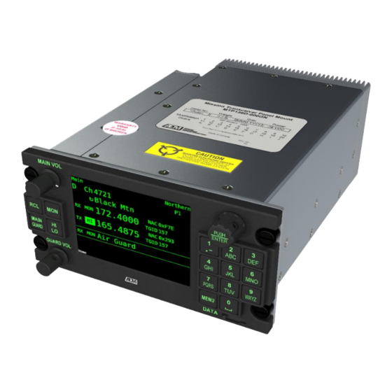
Introduction Information in this section consists of product description, design features, specifications, and regulatory statements for the MTP136D-000GN Mission Transceiver Panel Mount, herein subsequently referred to as the MTP136D. All derivative product information will be contained in the applicable manual supplement, which may be obtained from AEM as required. -
Page 9: Features
MTP136D Mission Transceiver Panel Mount Installation Manual Features The MTP136D is capable of half-duplex communication. The MTP136D is able to receive simultaneously on both the main and guard radio or transmit on one radio. The MTP136D is designed for high temperature operating environments allowing industry leading high power transmit durations. -
Page 10: Specifications
MTP136D Mission Transceiver Panel Mount Installation Manual Specifications All requirements and specifications relating to mechanical, electrical, or environmental performance can be found in the MTP136D-000GN-618-0 Declaration of Design and Performance. 1.4.1 Technical Characteristics Product Characteristic (L) 7.51” x (W) 4.96 x (H) 3.00” (length (L) -
Page 11: Summary Of Do-160G Environmental Test Conditions
MTP136D Mission Transceiver Panel Mount Installation Manual RF Characteristics Frequency Range: 136.0000 to 173.9975 MHz 50 nominal RF Impedance (In/Out): Modulation: FM (Analog) C4FM (Digital) Rated System Deviation: ±2.5 kHz max (Narrowband) ±5.0 kHz max (Wideband) Transmitter Characteristics RF Output Power: 1W, 10W Selectable ≥... -
Page 12: Product Approval/Certification
Declaration of Design and Performance to RTCA/DO-160G, TIA-603-E, TIA- 102.CAAB-D, and FCC/ISED Certification Rule 47, Part 22 & Part 90. FCC ID: ZC7-MTPB1GN ISED certification number: IC: 9601A-MTPB1GN HVIN: MTPB1GN Models (PMNs): MTP136D-000GN, MTP138-000GN FCC/ISED Emission Designators: 11K0F3E Analog Voice Analog FM... -
Page 13: Unit Nomenclature
Wideband Analog Bandwidth It is the responsibility of the installer or operator to determine if they meet exceptions to get these features enabled. To enable these features please contact AEM Technical Support at support@aem- corp.com with the serial number of the unit. -
Page 14: Regulatory Statements
MTP136D Mission Transceiver Panel Mount Installation Manual Regulatory Statements 1.9.1 ISED General Statements 1.9.1.1 ISED non-interference disclaimer This device contains licensed transmitter(s)/receiver(s) that comply with Innovation, Science and Economic Development Canada’s licensed RSS(s). Operation is subject to the following two conditions: This device may not cause interference. -
Page 15: Fcc Statements For Class A Digital Device
MTP136D Mission Transceiver Panel Mount Installation Manual d'un type et d'un gain maximal (ou inférieur) approuvé pour l'émetteur par Innovation, Sciences et Développement économique Canada. Dans le but de réduire les risques de brouillage radioélectrique à l'intention des autres utilisateurs, il faut choisir le type d'antenne et son gain de sorte que la puissance isotrope rayonnée équivalente (p.i.r.e.) ne dépasse pas l'intensité... -
Page 16: Health Canada Warning Statement
MTP136D Mission Transceiver Panel Mount Installation Manual inches (1.15 m) between the antenna and your body during normal operation. Users must follow the specific operating instructions for satisfying RF exposure compliance. Cet équipement est conforme aux limites d’exposition aux rayonnements FCC et ISED CNR-102 établies pour un environnement non contrôlé. -
Page 17: Fcc Narrowbanding Regulations
MTP136D Mission Transceiver Panel Mount Installation Manual 1. United States Federal Communications Commission, Code of Federal Regulations; 47 CFR § 1.1307, 1.1310, and 2.1091. 2. American National Standards Institute (ANSI) / Institute of Electrical and Electronic Engineers (IEEE) C95.1-1992. 3. Institute of Electrical and Electronic Engineers (IEEE) C95.1-1999 Edition. 4. -
Page 18: Section 2.0 Installation
This section assumes operational familiarity with the MTP136D. Please refer to MTP136D-000GN-813-0 Operating Guide for quick operating instructions. Unpacking and Inspection Unpack the equipment carefully. Inspect the unit visually for damage due to shipping and report all such claims immediately to the carrier involved. -
Page 19: Front Panel
MTP136D Mission Transceiver Panel Mount Installation Manual Front Panel Figure 2: MTP136D Front Panel Item Name Description Main Volume Knob Adjusts the volume of the main radio. Detent turns the (MAIN VOL) MTP136D OFF. Monitor Bypasses Squelch Threshold and Channel Signaling (MON) allowing all transmissions to be heard. -
Page 20: Warnings
MTP136D Mission Transceiver Panel Mount Installation Manual Warnings WARNING High volume settings can cause hearing damage. Set the headset volume control to the minimum volume setting prior to conducting tests, and slowly increase the headset volume to a comfortable listening level. Antennas WARNING To limit exposure to radio frequency fields that exceed exposure limits for... -
Page 21: Figure 3: Connector J1 And Antenna J2 Locations
MTP136D Mission Transceiver Panel Mount Installation Manual Figure 3: Connector J1 and Antenna J2 Locations Figure 4: MTP136D Outer Dimensions (inches) Rev. 1.00 April 22, 2024 Page 14 of 40 ENG-FORM: 815-0100.DOTX... -
Page 22: Figure 5: Mtp136D Behind Panel Dimensions (Inches)
MTP136D Mission Transceiver Panel Mount Installation Manual Figure 5: MTP136D Behind Panel Dimensions (inches) Rev. 1.00 April 22, 2024 Page 15 of 40 ENG-FORM: 815-0100.DOTX... -
Page 23: J1 System Interface Connector
MTP136D Mission Transceiver Panel Mount Installation Manual J1 System Interface Connector CAUTION Verify all airframe connections are checked against the Interconnect drawing. Pin # Pin Name Pin Description RX AUDIO HI Headset Audio Out HI RS485+ Serial Data Out PANEL LIGHTING 5V,14V, 28V Selectable CHAN/SELECT + Channel Select, Momentary Active Low... -
Page 24: Figure 7: Interconnect Drawing For Mtp136D
MTP136D Mission Transceiver Panel Mount Installation Manual RETROFIT COMPATIBLE INSTALLATION MTP136D-000GN Figure 7: Interconnect Drawing for MTP136D Rev. 1.00 April 22, 2024 Page 17 of 40 ENG-FORM: 815-0100.DOTX... -
Page 25: Figure 8: Alternate Interconnect Drawing For Mtp136D
MTP136D Mission Transceiver Panel Mount Installation Manual MTP136D-000GN Figure 8: Alternate Interconnect Drawing for MTP136D Rev. 1.00 April 22, 2024 Page 18 of 40 ENG-FORM: 815-0100.DOTX... -
Page 26: Figure 9: Interconnect Drawing Notes
MTP136D Mission Transceiver Panel Mount Installation Manual Figure 9: Interconnect Drawing Notes Rev. 1.00 April 22, 2024 Page 19 of 40 ENG-FORM: 815-0100.DOTX... -
Page 27: Additional Wiring Information
MTP136D Mission Transceiver Panel Mount Installation Manual 2.10 Additional Wiring Information Ensure wiring and coaxial cable materials used meet or exceed the aircraft certification basis. For some aircraft this includes Appendix F flammability requirements or later amendments of the applicable AWM and/or FAR design standards. -
Page 28: Pre-Installation Checks
MTP136D Mission Transceiver Panel Mount Installation Manual 2.12 Pre-Installation Checks Do not connect the MTP136D to the wiring harness until the checks in Table 7 and Table 8 are completed. Wiring Harness Connector Pin Continuity Check Continuity Continuity Expected Observed (No Power to Connector) (Yes/No) Pins 7 to 14... -
Page 29: Post-Installation Checks
MTP136D using Table 9: Post Installation Checks. MTP136D Functionality Check Pass Criteria Pass/Fail AEM Splash Boot up: Screen viewed Turn MAIN VOL knob clockwise past the detent before Home position to power on the MTP136D. -
Page 30: Post Installation Adjustments
MTP136D are disabled. If a Key Enabled Feature is required, a unique alpha- numeric key that is linked to the MTP136D’s serial number is necessary. To acquire the unique alpha-numeric key for the Key Enabled Feature please contact AEM Technical Support at support@aem-corp.com with the serial number of the MTP136D. - Page 31 MTP136D Radio Profile: Creation of a new profile: 1. Use the Radio Profile Editor on www.aem-corp.com 2. Enter profile information manually into the MTP136D. Cloning an existing profile: 3. Export an existing Radio Profile from an MTP136D (Cloning) to a USB drive.
-
Page 32: Table 13: Radio And Audio Adjustment
MTP136D Mission Transceiver Panel Mount Installation Manual 2.14.1.6 Radio and Audio Adjustments MTP136D audio settings may need to be adjusted to match the airframe audio management system. If required adjust the following settings and record the current setting in Table 13 below. MTP136D Headset Audio Expected Actual... -
Page 33: Table 14: Lighting Settings
MTP136D Mission Transceiver Panel Mount Installation Manual 2.14.1.7 Lighting Adjustments From the Admin Options screen under the “Lighting” heading, set the “Max Voltage” to applicable airframe panel lighting voltage level (28V/14V/5V) and save the setting. Current MTP136D Admin Options Screen Default Setting Setting Lighting: Max Voltage... -
Page 34: Table 16: Profile Hashes
MTP136D Mission Transceiver Panel Mount Installation Manual 2.14.1.9 Profile Hashes Settings, permissions, and channels in the MTP136D create unique identifiers called Profile Hashes. Profiles Hashes may be used to verify MTP136D Profiles across fleet installations or for troubleshooting purposes. Record the Profile Hashes into Table 16. -
Page 35: Airworthiness Approval Notes
Installation Manual. This MTP136D-000GN Installation Manual provides detailed installation instructions and wiring diagrams in Section 2.0 Installation. Power is supplied to the MTP136D-000GN through an [ ]-Amp circuit breaker. Aircraft equipment list, weights and balance amended. Compass compensation checked and found to conform to applicable regulations. - Page 36 Model and Serial Number] Content, Scope, Purpose and Arrangement: This document identifies the Instructions for Continued Airworthiness for an Anodyne Electronics Manufacturing Corp MTP136D-000GN installed in an [aircraft make and model]. Applicability: Applies to an Anodyne Electronics Manufacturing Corp MTP136D-000GN installed in an [aircraft make and model].
-
Page 37: Table 17: Continued Airworthiness
AC 43.13-1B. Special Tools N/A. For Commuter A. Electrical loads: MTP136D-000GN-618-0 Declaration of Category Aircraft Design and Performance. Only B. Methods of balancing flight controls: N/A. C. Identification of primary & secondary structures: N/A. -
Page 38: Post Installation Emi Test
The following channel information will need to be programmed into the MTP136D: Note: With an Agile Edit Key installed the following information can be programmed using the front panel on the MTP136D, otherwise the AEM Radio Profile Editor can be used to create a MTP136D.json file with the channel data. -
Page 39: Troubleshooting
Confirm if wideband channels are present in radio profile. Are wideband channels required? If so, confirm wideband key is installed. • Check the MTP136D_ImportLog located on the USB drive and contact AEM Technical Support. • Radio Fault Continuously Contact AEM Technical Support. Appears On Screen Note: The MTP136D is designed to automatically recover from a radio fault. -
Page 40: Table 19: Installation Troubleshooting Guide
Note: The MTP136D will automatically recover from power surges and under-voltage conditions. Contact AEM Technical Support at support@aem-corp.com if none of the above resolves the problem. Table 19: Installation Troubleshooting Guide End of Section 2.0 Installation... -
Page 41: Appendix A: Mtp136D Installation Options And Settings
MTP136D Mission Transceiver Panel Mount Installation Manual Appendix A: MTP136D Installation Options and Settings Admin Options Name Description Factory Range Default All Radios PTT Timeout 30s to 300s or None Disengages PTT after set time. Note: If set to “None” the MTP136D will disable the PTT Timeout. -
Page 42: User Options
MTP136D Mission Transceiver Panel Mount Installation Manual User Options Name Description Factory Range of Settings Default All Radios Auto TX On: Transmit power is set to the Active Channel On/Off Power transmit power on channel change or startup. Off: Transmit power persists across channel changes and power cycle. -
Page 43: Radio
MTP136D Mission Transceiver Panel Mount Installation Manual Go Home Off: Only return to home screen from exiting Radio Sel. Off/PTT/Radio current Menu. Sel./Both PTT: Activating PTT exits the current Menu and returns the display to the home screen. Radio Sel.: Pressing radio select (MAIN/GUARD) returns to home screen. -
Page 44: Appendix B: Environmental Qualification Form
MTP136D Mission Transceiver Panel Mount Installation Manual Appendix B: Environmental Qualification Form Rev. 1.00 April 22, 2024 Page 37 of 40 ENG-FORM: 815-0100.DOTX... - Page 45 MTP136D Mission Transceiver Panel Mount Installation Manual Rev. 1.00 April 22, 2024 Page 38 of 40 ENG-FORM: 815-0100.DOTX...
- Page 46 MTP136D Mission Transceiver Panel Mount Installation Manual Rev. 1.00 April 22, 2024 Page 39 of 40 ENG-FORM: 815-0100.DOTX...
- Page 47 MTP136D Mission Transceiver Panel Mount Installation Manual End of Appendix B Rev. 1.00 April 22, 2024 Page 40 of 40 ENG-FORM: 815-0100.DOTX...
Need help?
Do you have a question about the MTP136D-000GN and is the answer not in the manual?
Questions and answers