Table of Contents

Related Manuals for Toro 74991


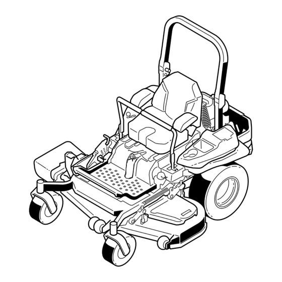
Summary of Contents for Toro 74991
- Page 1 Form No. 3396-233 Rev D Z Master ® Professional 5000 Series Riding Mower with 60in TURBO FORCE ® Side Discharge Mower Model No. 74991—Serial No. 315000001 and Up *3396-233* D Register at www.Toro.com. Original Instructions (EN)
- Page 2 Whenever you need service, genuine Toro parts, or ICES-002 additional information, contact an Authorized Service Dealer or Toro Customer Service and have the model Because in some areas there are local, state, or and serial numbers of your product ready.
-
Page 3: Table Of Contents
Contents Electrical System Maintenance ......46 Servicing the Battery......... 46 Servicing the Fuses .......... 48 Safety ............... 4 Jump-Starting the Machine....... 48 Safe Operating Practices........4 Drive System Maintenance ........50 Slope Indicator ........... 7 Checking the Seat Belt ........50 Safety and Instructional Decals ...... -
Page 4: Safety
Safety properly. Do not operate unless they are functioning properly. Improperly using or maintaining the machine can Operation result in injury. To reduce the potential for injury, comply with these safety instructions and always • Lightning can cause severe injury or death. If pay attention to the safety alert symbol, which lightning is seen or thunder is heard in the area, do means Caution, Warning, or Danger—personal... - Page 5 Toro equipment, count • Never fill containers inside a vehicle or on a truck on Toro genuine parts. When it comes to reliability, or trailer bed with a plastic liner. Always place Toro delivers replacement parts designed to the containers on the ground away from your vehicle exact engineering specifications of our equipment.
- Page 6 Hauling • Use care when loading or unloading the machine into a trailer or truck. • Use full width ramps for loading the machine into a trailer or truck. • Tie the machine down securely using straps, chains, cable, or ropes. Both front and rear straps should be directed down and outward from the machine.
-
Page 7: Slope Indicator
Slope Indicator g011841 Figure 3 This page may be copied for personal use. 1. The maximum slope you can safely operate the machine on is 15 degrees. Use the slope chart to determine the degree of slope of hills before operating. Do not operate this machine on a slope greater than 15 degrees. Fold along the appropriate line to match the recommended slope. -
Page 8: Safety And Instructional Decals
Safety and Instructional Decals Safety decals and instructions are easily visible to the operator and are located near any area of potential danger. Replace any decal that is damaged or lost. decal58-6520 58-6520 decal106-2655 1. Grease 106-2655 1. Warning-do not touch or approach moving belts; remove the ignition key and read the instructions before servicing or performing maintenance. - Page 9 decal110-2068 110-2068 1. Read the Operator's Manual. decal112-9028 112-9028 1. Warning—stay away from moving parts; keep all guards in place. decal107-3069 107-3069 1. Warning-there is no rollover protection when the roll bar is down. decal114-4466 2. To avoid injury or death from a rollover accident, keep the 114-4466 roll bar in the fully raised and locked position and wear the seat belt.
- Page 10 decal115-9625 115-9625 1. Parking 2. Parking brake—engaged brake—disengaged decal116-1716 decal117-0346 116-1716 117-0346 1. Fuel 6. Hour meter 1. Fuel leak hazard—read the Operator's Manual; do not 2. Empty 7. PTO attempt to remove the roll bar; do not weld, drill or modify the roll bar in any way.
- Page 11 decal117-3864 117-3864 1. Read the Operator’s 2. Fill to bottom of filler neck; Manual. warning—do not overfill the tank. decal126-4398 126-4398 1. Read the Operator’s 3. Unlock manual 2. Lock decal121-7586 121–7586 1. Fast 3. Slow 2. Variable speed control 4.
- Page 12 decaloemmarkt Manufacturer's Mark 1. Indicates the blade is identified as a part from the original machine manufacturer. decalbatterysymbols Battery Symbols Some or all of these symbols are on your battery 1. Explosion hazard 6. Keep bystanders a safe distance from the battery. 7.
- Page 13 decal132-5063 132-5063 1. Cam lock 2. Cam unlock decal132-5067 132–5067...
- Page 14 decal132-0871 132-0871 Note: This machine complies with the industry standard stability test in the static lateral and longitudinal tests with the maximum recommended slope indicated on the decal. Review the instructions for operating the machine on slopes in the Operator’s Manual as well as the conditions in which you would operate the machine to determine whether you can operate the machine in those conditions on that day and at that site.
-
Page 15: Product Overview
Product Overview g013112 Figure 5 1. PTO Switch 4. Hour meter/Safety-interlock display/Fuel gauge 2. Throttle control 5. Ignition switch g029631 Figure 4 3. Malfunction indicator light 6. Fuses (MIL) 8. Rear, shock assembly 1. Side-discharge deflector 2. Height-of-cut deck-lift 9. Seat belt pedal Fuel Gauge 3. -
Page 16: Specifications
Throttle Control enhance and expand its capabilities. Contact your Authorized Service Dealer or Distributor or go to The throttle control is variable between Fast and www.Toro.com for a list of all approved attachments Slow. and accessories. Blade-Control Switch (PTO) Specifications The blade-control switch (PTO) is used to engage the electric clutch and drive the mower blades. -
Page 17: Operation
Operation DANGER In certain conditions during fueling, static Note: Determine the left and right sides of the electricity can cause a spark which can ignite machine from the normal operating position. the gasoline vapors. A fire or explosion from gasoline can burn you and others and can Adding Fuel damage property. - Page 18 Filling the Fuel Tank chance of varnish deposits in the fuel system, use fuel stabilizer at all times. Park the machine on level ground. Shut the engine off and set the parking brake. Clean around the fuel-tank cap and remove it. Add regular unleaded gasoline to the fuel tank until the level is 6 to 13 mm (1/4 to 1/2 inch) below the bottom of the filler neck.
-
Page 19: Checking The Engine-Oil Level
Checking the Engine-Oil Level Before you start the engine and use the machine, check the oil level in the engine crankcase; refer to Checking the Engine-Oil Level (page 40). Breaking in a New Machine New engines take time to develop full power. Mower decks and drive systems have higher friction when new, placing additional load on the engine. -
Page 20: Think Safety First
g029797 Figure 9 g000963 Figure 10 1. Mower deck 1. Safe Zone-use the 3. Water Z Master here on slopes less than 15 degrees or flat areas. Think Safety First 2. Danger Zone- use a walk behind mower and/or a Please read all safety instructions and symbols in the hand trimmer on slopes greater than 15 degrees,... -
Page 21: Operating The Mower Blade-Control Switch (Pto)
Setting the Parking Brake WARNING The parking brake may not hold machine parked on a slope and could cause personal injury or property damage. Do not park on slopes unless the wheels are g008945 Figure 14 chocked or blocked. Disengaging the Blade-Control Switch (PTO) g029632 Figure 12... -
Page 22: Using The Fuel-Shutoff Valve
Starting and Stopping the period between attempts. Failure to follow these instructions can burn out the starter Engine motor. Note: Additional starting cycles may be required when starting the engine for the first Starting the Engine time after the fuel system has been completely Raise the ROPS up and lock into place, sit on without fuel. -
Page 23: The Safety-Interlock System
Stopping the Engine The Safety-Interlock System CAUTION Children or bystanders may be injured if they CAUTION move or attempt to operate the machine while it is unattended. If safety-interlock switches are disconnected or damaged the machine could operate Always remove the ignition key and set the unexpectedly causing personal injury. -
Page 24: Driving Forward Or Backward
Using the Motion-Control Levers Test the safety-interlock system before you use the machine each time. If the safety system does not operate as described below, have an Authorized Service Dealer repair the safety system immediately. Sitting on the seat, engage the parking brake and move the blade-control switch (PTO) to on. -
Page 25: Stopping The Machine
Stopping the Machine To stop the machine, move the traction control levers to neutral and to the locked position, disengage the power take-off (blade-control switch (PTO), and turn the ignition key to off. Set the parking brake when you leave the machine; refer to Setting the Parking Brake in Operation. - Page 26 Adjusting the Height-of-Cut Pin The height of cut is adjusted from 25 to 140 mm (1 to 5-1/2 inches) in 6 mm (1/4 inch) increments by moving the clevis pin into different hole locations. Move the transport lock to the lock position. Push on the deck lift pedal with your foot, and raise the mower deck to the transport position (also the 140 mm (5-1/2 inch) cutting-height...
-
Page 27: Adjusting The Anti-Scalp Rollers
g029956 Figure 28 1. Anti-scalp roller 3. Flange nut g029840 2. Bushing 4. Bolt Figure 26 1. Deck lift pedal 3. Transport lock 2. Height-of-cut pin Adjusting the Anti-Scalp Rollers Whenever you change the height of cut, it is recommended to adjust the height of the anti-scalp rollers. -
Page 28: Positioning The Flow Baffle
• Allows increased ground speed in heavy conditions. Position A • This position is similar to the benefits of the Toro SFS mower. This is the full rear position. The suggested use for this position is as follows. • Use for short, light grass-mowing conditions. -
Page 29: Positioning The Seat
Positioning the Seat 2 shock assemblies is the easiest and quickest adjustment for changing the suspension system. Position the suspension system where you are most The seat can move forward and backward. Position comfortable. the seat where you have the best control of the machine and are most comfortable. -
Page 30: Using The Drive Wheel Release Valves
Adjust the rear, shock assemblies (Figure 37). To adjust the front, shock assembly, open the floor pan and adjust it by using a spanner wrench (Toro part no. 132–5069) or a slip-joint pliers (Figure 38). g030024 g030049 Figure 38 1. Middle position 3. -
Page 31: Using The Side Discharge
neutral-locked position and apply parking brake. DANGER Remove the key. Without a grass deflector, discharge cover, or Rotate the release valve levers vertically to push complete grass catcher assembly mounted in the machine. This allows hydraulic oil to by-pass place, you and others are exposed to blade the pump enabling the wheels to turn (Figure contact and thrown debris. -
Page 32: Transporting The Machine
Transporting the Machine Loading the Machine Use a heavy-duty trailer or truck to transport the Use extreme caution when loading or unloading machine. Ensure that the trailer or truck has all machines onto a trailer or a truck. Use a full-width necessary brakes, lighting, and marking as required ramp that is wider than the machine for this procedure. - Page 33 WARNING Loading a machine onto a trailer or truck increases the possibility of tip-over and could cause serious injury or death. • Use extreme caution when operating a machine on a ramp. • Ensure that the ROPS is in the up position and use the seat belt when loading or unloading the machine.
-
Page 34: Operating Tips
This also helps disperse clippings which as necessary. If a blade is damaged or worn, replace it enhances decomposition and fertilization. immediately with a genuine TORO replacement blade. Mow at Correct Intervals Normally, mow every four days. But remember, grass grows at different rates at different times. -
Page 35: Maintenance
• Adjust the caster pivot bearing. Every 500 hours • Check the parking brake adjustment. • Change the hydraulic filters and hydraulic oil when using Toro® HYPR-OIL™ 500 hydraulic oil (more often in dirty or dusty conditions). • Replace the inner air filter. -
Page 36: Lubrication
CAUTION If you leave the key in the ignition switch, someone could accidently start the engine and seriously injure you or other bystanders. Remove the key from the ignition before you do any maintenance. Lubrication Lubricating the Machine Grease more frequently when operating conditions are extremely dusty or sandy. - Page 37 g029643 Figure 47 g009029 Figure 45 Grease the drive belt idler arm (Figure 45). g009030 Figure 46 Remove the dust cap and adjust the caster pivots. Note: Keep the dust cap off until greasing is complete. Refer to Adjusting the Caster Pivot Bearing (page 52).
-
Page 38: Lubricate The Caster Wheel Hubs
Lubricate the Caster Wheel With the open end of the wheel facing up, fill the area inside the wheel around the axle full of Hubs general-purpose grease. Insert the second bearing and new seal into the Service Interval: Yearly wheel. Stop the engine, wait for all moving parts to stop, Apply a thread locking adhesive to the second and remove the key. -
Page 39: Engine Maintenance
Engine Maintenance WARNING Contact with hot surfaces may cause personal injury. Keep hands, feet, face, clothing, and other body parts away the muffler and other hot surfaces. Servicing the Air Cleaner g030481 Figure 49 Service Interval: Every 150 hours 1. Cover 5. -
Page 40: Servicing The Engine Oil
Installing the Filters Servicing the Engine Oil Important: To prevent engine damage, always Oil Type: Detergent oil (API service class SL, SM, operate the engine with both air filters and cover SN, or higher) installed. Oil Capacity: with a filter change, 1.7 L (1.8 US qt); If installing new filters, check each filter for with no filter change, 1.4 L (1.5 US qt) shipping damage. - Page 41 Changing the Engine Oil Service Interval: Every 100 hours (more often in dirty or dusty conditions). Note: Dispose of the used oil at a recycling center. Park the machine so that the rear is slightly g029644 lower than the front to ensure that the oil drains completely.
- Page 42 Slowly pour approximately 80% of the specified oil into the filler tube and slowly add the additional oil to bring it to the Full mark (Figure 53). g029644 g027660 Figure 53 Start the engine and drive to a flat area. Check the oil level again.
-
Page 43: Servicing The Spark Plugs
Servicing the Spark Plugs Service Interval: Every 200 hours—Check and gap the spark plug. Make sure that the air gap between the center and side electrodes is correct before installing the spark plugs. Use a spark-plug wrench for removing and g029644 installing the spark plugs and a gapping tool/feeler gauge to check and adjust the air gap. - Page 44 Checking the Spark Plugs Important: Replace the spark plugs when they have: a black coating, worn electrodes, an oily film, cracks or reuse is questionable. If you see light brown or gray on the insulator, the engine is operating properly. A black coating on the g029645 insulator usually means that the air cleaner is dirty.
-
Page 45: Check Spark Arrester (If Equipped)
Check Spark Arrester (if Fuel System equipped) Maintenance Service Interval: Every 50 hours WARNING WARNING Fuel system components are under high pressure. The use of improper components Hot exhaust system components may ignite can result in system failure, gasoline leakage, gasoline vapors even after the engine is and possible explosion. -
Page 46: Servicing The High-Pressure Fuel Filter
Electrical System Maintenance Servicing the Battery Service Interval: Monthly WARNING CALIFORNIA Proposition 65 Warning Battery posts, terminals, and related accessories contain lead and lead g008963 compounds, chemicals known to Figure 60 the State of California to cause 1. Fuel filter 3. - Page 47 WARNING Incorrect battery cable routing could damage the machine and cables causing sparks. Sparks can cause the battery gases to explode, resulting in personal injury. • Always disconnect the negative (black) g029644 battery cable before disconnecting the positive (red) cable. •...
-
Page 48: Servicing The Fuses
Charging the Battery Servicing the Fuses The electrical system is protected by fuses. It requires WARNING no maintenance; however, if a fuse blows check the Charging the battery produces gases that can component/circuit for a malfunction or short. explode. The fuses are located on right hand console next to the seat (Figure 63). - Page 49 DANGER Jump-starting a weak battery that is cracked or frozen, or has a low electrolyte level or an open/shorted battery cell can cause an explosion resulting in serious personal injury. Do not jump-start a weak battery if these conditions exist. Make sure that the booster battery is a good and g012785 Figure 64...
-
Page 50: Drive System Maintenance
Drive System Start the vehicle and remove the cables in the reverse order of connection (the engine block Maintenance (black) connection is the first to disconnect). Checking the Seat Belt Service Interval: Before each use or daily Visually inspect seat belt for wear, cuts, and proper operation of retractor and buckle. -
Page 51: Adjusting The Tracking
Tighten the stop plate (Figure 68). g029647 Figure 68 Left control lever shown 1. Control lever 3. Stop plate 2. Bolt Checking the Tire Pressure Service Interval: Every 50 hours/Monthly (whichever comes first) g008943 Figure 67 Maintain the air pressure in the rear tires at 90 kPa (13 psi). -
Page 52: Checking The Wheel Lug Nuts
Checking the Wheel Lug Important: Make sure that the spring washers are installed correctly as shown in Nuts Figure Install the dust cap (Figure 71). Check and torque the wheel lug nuts to 122 to 129 N-m (90 to 95 ft-lb). Checking the Wheel Hub Slotted Nut Service Interval: After the first 100 hours... - Page 53 Removing the Clutch Shim Note: Do not discard the shim until proper clutch function has been confirmed. Stop the engine, wait for all moving parts to stop, and remove the key. Engage the parking brake. Allow the machine to cool completely before starting these instructions.
-
Page 54: Cooling System Maintenance
Cooling System • If the gap is less than 0.010 inch, then reinstall the shim and reference the Maintenance Troubleshooting section. • If the gap is sufficient, proceed to the safety check in step F. Cleaning the Engine Screen Perform the following safety check: and Engine-Oil Cooler Sit on the seat and start the engine. -
Page 55: Check And Clean The Hydraulic-Unit Shrouds
g029645 g004218 g009920 Figure 79 Figure 80 1. Engine guard 4. Fan housing 1. Hydraulic unit shrouds 2. Engine air intake screen 5. Screw 3. Bolt Check and Clean the Hydraulic-Unit Shrouds Service Interval: Before each use or daily Disengage the PTO and set the parking brake. Stop the engine, remove the key, and wait for all moving parts to stop before leaving the operating position. -
Page 56: Brake Maintenance
Brake Maintenance Adjusting the Parking Brake Service Interval: After the first 100 hours Every 500 hours thereafter Check to make sure the brake is adjusted properly before adjusting. Note: This procedure must be followed after the first 100 hours or when a brake component has been removed or replaced. -
Page 57: Belt Maintenance
Belt Maintenance Inspecting the Belts Service Interval: Every 50 hours Check the belts for squealing when the belt is rotating, blades slipping when cutting grass, frayed belt edges, burn marks, and cracks. These are signs of a worn mower belt; replace the mower belt if any of these conditions are evident. -
Page 58: Replacing The Hydraulic Pump Drive Belt
g027730 Figure 84 g009039 1. Position the belt cover 3. Ensure that the tab is Figure 85 under the metal catch 1. Idler pulley 5. Left-hand hydraulic pump 2. Slide belt cover under the pulley side catches 2. Clutch pulley 6. -
Page 59: Controls System Maintenance
Controls System Maintenance Adjusting the Control Handle Position There are 2 height positions for the control levers: high and low. Remove the bolts to adjust the height for the operator. Disengage the PTO, move the motion-control levers to the neutral-locked position, and set the parking brake. -
Page 60: Adjusting The Motion-Control Damper
Start the engine. Raise the deck and install the height-of-cut pin. Check that the machine does not creep in Note: The brake must be engaged, and the neutral with the parking brake disengaged. motion-control levers out, to start the engine. The operator does not have to be in the seat because of the jumper wire being used. -
Page 61: Hydraulic System Maintenance
Hydraulic System Maintenance Servicing the Hydraulic System Hydraulic Oil Type: Toro ® HYPR-OIL ™ 500 hydraulic g008621 oil or Mobil ® 1 15W-50. Figure 90 Important: Use oil specified. Other fluids could 1. Flanged nut 2. Jam nut cause system damage. - Page 62 Mobil ® 1 oil (more often in dirty or dusty conditions). Every 500 hours—Change the hydraulic filters and hydraulic oil when using Toro ® HYPR-OIL ™ 500 hydraulic oil (more often in dirty or dusty conditions).
-
Page 63: Mower Deck Maintenance
Mower Deck Maintenance Leveling the Mower Deck Setting Up the Machine Note: Ensure that the mower deck is leveled before matching the height of cut (HOC). Position the machine on a flat surface. Disengage the blade-control switch (PTO), move the motion-control levers to the neutral-locked position and set the parking brake. - Page 64 Insert the height-adjustment pin into the 7.6 cm (3 inch) cutting-height position. Release the transport lock and allow the deck to lower to the cutting height. Raise the discharge chute. On both sides of the deck, measure from the level surface to the front tip of the blade (Postion A).
-
Page 65: Servicing The Cutting Blades
If a blade is Stop the engine, remove the key, and wait damaged or worn, replace it immediately with a for all moving parts to stop before leaving the genuine Toro replacement blade. For convenient operating position. - Page 66 To ensure optimum performance and continued safety conformance of the machine, use genuine Toro replacement blades. Check the balance of the blade by putting it on a Replacement blades made by other manufacturers...
- Page 67 Installing the Blades Install the blade onto the spindle shaft (Figure 104). Important: The curved part of the blade g000277 Figure 103 must be pointing upward toward the inside of the mower to ensure proper cutting. 1. Blade 2. Balancer Install the spring disk and the blade bolt.
-
Page 68: Removing The Mower Deck
Removing the Mower Deck Before servicing or removing the mower deck, the spring-loaded deck arms must be locked out. WARNING Deck lift arm assemblies have stored energy. Removing the deck with out releasing the stored energy can cause serious injury or death. -
Page 69: Replacing The Grass Deflector
g029652 Figure 106 1. Right stabilizer 2. Deck strut (right side shown) 3. Remove the rear deck lift attachment shoulder bolt and nut. 4. Remove the front deck lift attachment shoulder bolt and nut. g009038 Raise the deck struts and secure them in the up Figure 105 position. -
Page 70: Cleaning
Cleaning Cleaning under the Mower Service Interval: Before each use or daily Disengage the blade-control switch (PTO), move the motion-control levers to the neutral-locked position and set the parking brake. Stop the engine, remove the key, and wait for all moving parts to stop before leaving the operating position. -
Page 71: Storage
Storage Run the engine to distribute conditioned fuel through the fuel system (5 minutes). Stop the engine, allow it to cool, and drain Cleaning and Storage the fuel tank; refer to Servicing the Fuel Tank (page 46). Disengage the power take off (blade-control switch (PTO), set the parking brake, and turn Restart the engine and run it until it stops. -
Page 72: Troubleshooting
Troubleshooting Problem Possible Cause Corrective Action The malfunction Indicator Light (MIL) 1. The engine is too hot. 1. Turn the engine off and let it cool. comes on. 2. There is old gas in the gas tank. 2. Use new gas. 3. - Page 73 Problem Possible Cause Corrective Action The engine loses power. 1. The engine load is excessive. 1. Reduce the ground speed. 2. The air cleaner is dirty. 2. Clean the air-cleaner element. 3. The oil level in the crankcase is low. 3.
- Page 74 Problem Possible Cause Corrective Action The clutch does not engage. 1. The fuse is blown. 1. Replace the fuse. Check the coil resistance, battery charge, charging system, and wiring connections, and replace components if necessary. 2. There is low voltage supply at the 2.
-
Page 75: Schematics
Schematics g013119 Wire Diagram (Rev. A) - Page 76 Customers who have purchased Toro products outside the United States or Canada should contact their Toro Distributor (Dealer) to obtain guarantee policies for your country, province, or state. If for any reason you are dissatisfied with your Distributor's service or have difficulty obtaining guarantee information, contact the Toro importer. If all other remedies fail, you may contact us at Toro Warranty Company.
Need help?
Do you have a question about the 74991 and is the answer not in the manual?
Questions and answers