Table of Contents
Advertisement
Quick Links
Advertisement
Table of Contents

Summary of Contents for Lilee Systems SDR-2400
- Page 1 SDR-2400 SM-SDR-2400 User Guide...
- Page 2 Copyright Copyright © 2019 LILEE Systems, Ltd. LILEE Systems, TransAir, and the LILEE Systems logo are trademarks of LILEE Systems. All other brands, products, or service names are or may be trademarks or service marks of their respective owners. Name: SDR-2400/SM-SDR-2400 User Guide...
-
Page 3: Product Images
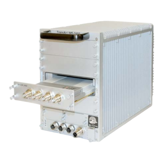
Product images Figure 1: SDR-2400 Figure 2: SM-SDR-2400 Figure 3: LMS-2450-ME-100 chassis with SM-SDR-2400 SDR-2400/SM-SDR-2400 User Guide Product images | 3... -
Page 4: Table Of Contents
Contents Product images Figure 1: SDR-2400 Figure 2: SM-SDR-2400 Figure 3: LMS-2450-ME-100 chassis with SM-SDR-2400 Contents Before You Begin Safety considerations ESD notice FCC/IC approval notice, Part 15 notice Federal Communications Commission interference statement 15.21: Approved antennas Equipment modifications RF exposure warning... - Page 5 Interface Panel and Ports SM-SDR-2400 front panel view Antenna ports LED indicators LED status light descriptions MIMO 4x4 mode MIMO 2x2, all modes (dual, 1/2, or 3/4) Power (all MIMO 2x2 and 4x4 modes) Assembly and Installation Faceplate assembly for SM-SDR-2400...
-
Page 6: Before You Begin
Do not apply voltage levels that exceed the specified voltage range. Doing so may cause fire and/or electrical shock. Do not open the chassis when the SDR-2400/SM-SDR-2400 is running: Electric shocks can occur. If considerable amounts of dust, water, or fluids enter the SDR-2400/SM-SDR-2400, turn off the power supply immediately, unplug the power cord, and contact the distributor or sales rep- resentative. -
Page 7: Fcc/Ic Approval Notice, Part 15 Notice
Be aware that any changes or modifications to this equipment not expressly approved by the party responsible for compliance (in the respective country of use) could void the user’s authority to operate the equipment. SDR-2400/SM-SDR-2400 User Guide FCC/IC approval notice, Part 15 notice | 7... -
Page 8: Rf Exposure Warning
本 模 組 於 取 得 認 證 後 將 依 規 定 於 模 組 本 體 標 示 審 驗 合 格 標 籤 , 並 要 求 最 終 產 品 平 台 廠 商 (OEM Integrator)於 最 終 產 品 平 台 (End Product)上 標 示 “本 產 品 內 含 射 頻 模 組 , 其 NCC型 式 認 證 號 碼 為 : CCAH19LP1380T7 (SDR-2400), CCAH19LP1381T9 (SM-SDR-2400) 8 | RF exposure warning... -
Page 9: Introduction
Introduction The LILEE Systems SDR-2400/SM-SDR-2400 is a MIMO 4x4 software-defined radio module for LMS- 2450-ME-100 or other compatible chassis. It can be configured in either base station mode or client mode. It operates in the 2.4G Hz ISM band, with typical bandwidth of 20 MHz and data rate up to 200 Mbps. -
Page 10: Specifications
Specifications Radio interfaces Frequency band: 2.4000-2.4835 GHz ISM Band Channel bandwidth: 20 MHz Mode of operation: TDD/TDMA MIMO: 4x4, dual 2x2 diversity Data rate: up to 200Mbps Modulation: OFDM with BPSK, QPSK, 16 QAM, 64 QAM FEC: Convolutional code with coding rate 1/2, 2/3, 3/4, and 5/6 Power increments: 0.25 dB Transmitter stability into VSWR: 3:1 RF ports impedance: 50 Ohms... -
Page 11: Mechanical Drawings And Dimensions
Mechanical drawings and dimensions Top View SDR-2400/SM-SDR-2400 User Guide Mechanical drawings and dimensions | 11... -
Page 12: Side View (Right)
Side View (Right) Front View 12 | Side View (Right) -
Page 13: Interface Panel And Ports
Interface Panel and Ports This chapter presents illustrations of all connectors and ports on the SM-SDR-2400, as well as their descriptions. SM-SDR-2400 front panel view Antenna ports There are 4 TNC-female antenna connectors on the front panel. For best performance, you should use four identical antennas with same cable type and cable length. -
Page 14: Led Status Light Descriptions
LED status light descriptions The front panel of the SM-SDR-2400 has a number of LED indicators. The following tables explain the meaning of each light, according to which radio mode is in use. MIMO 4x4 mode Light Description Green, blinking @ 15 Hz (all ports) Active T/R ... -
Page 15: Assembly And Installation
Assembly and Installation Faceplate assembly for SM-SDR-2400 Please refer to the following figures for faceplate installation. Front panel assembly SDR-2400/SM-SDR-2400 User Guide Assembly and Installation | 15... -
Page 16: Bracket Assembly
Bracket assembly 16 | Bracket assembly... -
Page 17: Connecting Rf Cables And Attaching Front Panel
Connecting RF cables and attaching front panel SDR-2400/SM-SDR-2400 User Guide Connecting RF cables and attaching front panel | 17... -
Page 18: Bracket Assembly
Bracket assembly 18 | Bracket assembly... -
Page 19: Cover Assembly
Cover assembly SDR-2400/SM-SDR-2400 User Guide Cover assembly | 19... -
Page 20: Complete Assembly
Complete assembly The unit should look like this when assembly is complete. 20 | Complete assembly... -
Page 21: Chassis Installation
Please refer to LMS-2450-ME-100 Hardware Installation Guide for chassis installation. Smart module installation To install the SM-SDR-2400 smart module, follow these steps: 1. Disconnect power from the LMS-2450-ME-100. 2. If you are replacing an existing smart module, remove all connections from any ports. -
Page 22: Configuring The Sdr-2400/Sm-Sdr-2400
4. The base station exchanges device information with the locomotive (MAC address, client ID, and so forth). Then the link-up process completes. Both SDR-2400 should be able to ping each other. 22 | Configuring the SDR-2400/SM-SDR-2400... -
Page 23: Base Station And Client Modes
Set MIMO 2X2 mode, using antenna 3/4 > cfg_ad9361 pa 0011 > reg_wr $REG_AD9361_CFG1 0x130130 Set MIMO dual 2X2 mode > cfg_ad9361 pa 1111 > reg_wr $REG_AD9361_CFG1 0x130130 Set MIMO 4X4 mode > cfg_ad9361 pa 1111 SDR-2400/SM-SDR-2400 User Guide Base station and client modes | 23... - Page 24 www.lileesystems.com LILEE Systems (Headquarters) LILEE Systems (Asia Pacific) 91 E Tasman Dr 9F, No.3-2, YuanQu St., Nangang San Jose, CA 95134 Taipei, Taiwan 11503...
Need help?
Do you have a question about the SDR-2400 and is the answer not in the manual?
Questions and answers