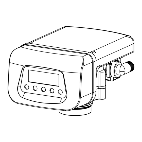
Summary of Contents for JY GL-1 Series
- Page 1 GL-1 Series Filter valve Installation, use and maintenance manual (GL2-1、GL4-1、GL10-1、GL10-1S) Scan Qr code for the latest GL-1 shifting animation...
-
Page 2: The Operation Button
GL-1 Service manual Ⅰ、Operating Board 1 Instructions of the LCD display controller PIC1:LCD panel The operation button: switch; setting; switch; :Manual :Parameter :Mode :Move to the next digit; :Plus 1 A、Unlock:Press “ ”&“ ” buttons at the same time,The key lock is unlocked,Displaying”... - Page 3 GL-1 Service manual Meter mode“ ”interface The current:B.wash(back wash) S:0125: Set of backwash water. D:0125:Decrementing state, decrementing to zero and switching to the next station. 00.00t/h:Inlet water flow rate. 00000.0t:Cumulative water through inlet. The current:Wash S:0100: Set of washing water. D:0100:Decrementing state, decrementing to zero and switching to the next station.
- Page 4 GL-1 Service manual Parameter set Meter mode“ ”setting Time mode“ ”setting...
-
Page 5: Led Display
GL-1 Service manual 2 LED Controller Operation instruction PIC2: LED panel LED Display Day\hour\min\M3\L\M3/H Is the unit of time or flow, respectively, with the content, as suggested by the light :Flow mode symbol :Time mode symbol :Backwash working station indicator :Washing station indicator Run::Run working station indicator :Enter to setting state symbol... - Page 6 GL-1 Service manual :Move to the next digit; :+1 Set the parameters defined C1: B.wash station, setting amount of water for backwash. Unit: L, C2: Wash station, setting amount of water for wash. Unit: L, C3: Run station setting amount of water for running. Unit: L, C4: Time mode, B.wash station setting time.
- Page 7 GL-1 Service manual Unlock state Press“ ”enter setting interface, Press” ”, Modify the flashing digital. Press“ ”enter to next digital , press“ ”to confirm the setting to enter to next page C2,To modify the C4 subsequent parameters, please press " "...
-
Page 8: External Control Interface
GL-1 Service manual Ⅱ、Input/output control instructions 1、Interlock line connection as below Pic3: Interlock 2.External control interface In RUN station, The valve can be controlled into backwash through the external other control system. Pic4:External control input 3.Relay output interface and mode(CC) A、The contact capacity of the relay is 5A/250V. - Page 9 GL-1 Service manual Mode B.wash wash Valve shifting × × × × × × × × × × × × × × × Applications Mode Inlet solenoid valve mode: As shown in pic 5. Backwash booster pump mode: This function is used to initiate a booster pump start-up when the control valve begins its Backwash.
- Page 10 GL-1 Service manual Pic5:Mode(0): Solenoid valve liquid level switch and feed pump Water pressure will release when the control valve is shifting and the solenoid valve will cut off.
- Page 11 GL-1 Service manual Pic6:Mode(4): Run simultaneously and backwash separately Ⅲ、Installation Pic7:GL2-1 Control valve size...
- Page 12 GL-1 Service manual Pic8:GL4-1 Control valve size Note: 1, The water must be installed filters, lest cause valve core fault and water distributor congestion. 2, Pipe valve specifications is not less than control valve in and out of the size.Place indoors, the ambient temperature is not lower than 0 ℃ . Water inlet temperature 0 ℃...
- Page 13 GL-1 Service manual high, there should be no corrosive chemical gas around, to avoid strong electromagnetic interference to affect the power supply of the control valve. 5. Floor drain or trench drainage shall be set around the equipment to avoid accidental water leakage causing the floor and other indoor items to be flooded.
- Page 14 GL-1 Service manual Pic10:GL10-1S Control valve size...
- Page 15 GL-1 Service manual Pic11:GL10-1S side loading valve set Ⅳ Curve of Flow and Pressure for the Valve Pic12:GL2-1 Curve of Flow and Pressure...
- Page 16 GL-1 Service manual Pic13:GL4-1 Curve of Flow and Pressure Pic14:GL10-1(GL10-1S) Curve of Flow and Pressure...
- Page 17 GL-1 Service manual Ⅴ Control valve structure Pic15:GL2-1\GL4-1 Control valve structure...
- Page 18 GL-1 Service manual Pic16:GL10-1 Control valve structure...
- Page 19 GL-1 Service manual Pic17:GL10-1S Control valve structure VI 、Explode drawing(GL4-1 example)...
- Page 20 GL-1 Service manual Pic18:Explode drawing(GL4-1 example)...

Need help?
Do you have a question about the GL-1 Series and is the answer not in the manual?
Questions and answers