
Related Manuals for Exact Imaging ExactVu

Summary of Contents for Exact Imaging ExactVu
- Page 1 Service Manual for ExactVu™ High Resolution Micro-Ultrasound System Part Number 7007 Revision 2.6...
- Page 2 Software: Applicable for ExactVu™ Versions 2.5.5, 2.6.0, 2.8.x, 2.9.x, 3.0.x DICOM Conformance Statement The DICOM Conformance Statement for ExactVu specifies the capabilities and properties by which ExactVu stores ultrasound studies to a PACS server. The latest version is accessible at the following link: https://www.exactimaging.com/dicom-conformance-statement Exact Imaging...
-
Page 3: Table Of Contents
Starting the ExactVu System ......................29 Turning the ExactVu System Off ..................... 29 Setting up the Control Panel/Monitor Platform ................29 Connecting an (Optional) Second Monitor (ExactVu 2.6 hardware versions only) ....30 Unpacking and Connecting the Foot Pedal ................32 3.10 Unpacking and Connecting the Transducers ................ - Page 4 Servicing the IO Plate ........................140 Servicing the Wheel Base ......................140 Servicing the Transducer and Transducer Connector .............. 140 Servicing the ICL (Inrush Current Limiter) (ExactVu 2.5 HW versions only) ......141 Chapter 4 Testing the ExactVu System ......................142 Testing the System Cart .........................
- Page 5 Service Manual for ExactVu™ High Resolution Micro-Ultrasound System Revision 2.6 Hardware Communication Test ....................150 General Imaging Test ........................151 Safety Test ............................152 Testing the Computer Unit ........................152 Operating System Settings Verification ..................152 Hardware Communication Test ....................153 General Imaging Test ........................
-
Page 6: Introduction
ExactVu 2.5 or ExactVu 2.6/2.9 version of the hardware. HWNOTE EN-N175 The instructions in this manual make reference to information that may be found in the other ExactVu manuals and guides. Before servicing the equipment, please ensure you have access to these documents. - Page 7 EV-SYS-100: ExactVu™ Micro-Ultrasound Imaging System (100V) Problems reported by ExactVu operators may be resolved remotely by email, by telephone support, local Technical Support trained by Exact Imaging, or by means of an on-site visit by Technical Support personnel when necessary.
-
Page 8: Exactvu System Overview
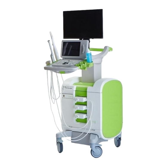
Castor locking Thermal printer mechanism (optional) Foot pedal and foot System power control pedal cable management clips (not Castors pictured) Figure 1: ExactVu™ High Resolution Micro-Ultrasound System: Front View Exact Imaging Page 8 of 201... - Page 9 EN-W3 system. If components other than those specified in this section are connected to the system, the ExactVu software may fail and cause injury to the patient or operator. The ExactVu micro-ultrasound system consists of the following sub-assemblies: • ExactVu System Cart •...
- Page 10 Power Box (contains the power supply unit and isolation transformer) • System Cabling • EV29L Transducer • EV9C Transducer • EV5C Transducer • Transducer Connector • Foot Pedal Figure 3: ExactVu Major Architecture Components – ExactVu System Hardware Version 2.5 Exact Imaging Page 10 of 201...
-
Page 11: Exactvu System Cart
These sub-assemblies are described in the following sections. 1.1 ExactVu System Cart The ExactVu system cart houses the electronics, computer unit, power box, and system cabling. The user interface includes a control panel with a trackball, a touch screen and a monitor. - Page 12 The ExactVu monitor is pre-configured by Exact Imaging for optimal imaging settings. 1.1.4 Cooling System The ExactVu system cart includes a system of cooling fans, air guides, and air vents to control the temperature of the various electronics. Exact Imaging...
-
Page 13: Exactvu Software
1.2 ExactVu Software 1.2.1 Modes of Operation The imaging modes available on the ExactVu micro-ultrasound system are dependent on the transducer in use. When using the EV29L side-fire transducer, 2D Mode imaging is available as the primary form of B- Mode operation. -
Page 14: Beamformer Control Board
The beamformer control board (BCB) is contained within the computer unit. It allows communication between the computer unit and the channel boards. The BCB in ExactVu System Version 2.6/2.9 system provides version and serial number by means of nonvolatile memory (EEPROM). -
Page 15: Transducer Connector
(specific to each transducer), 2x control board (for the EV29L transducer), and a plug board. 1.11 Foot Pedal The ExactVu foot pedal is a single-button pedal that may be configured by the operator for saving single frames or cine images. The foot pedal connects to the USB connector at the bottom rear of the ExactVu system cart (refer to Figure 5). -
Page 16: Ev29L Sterile Transrectal Needle Guide For Procedures Using The Ev29L Transducer
Foot pedal button Figure 5: Foot Pedal 1.11.1 Foot Pedal Cable Management The foot pedal cable is secured to the ExactVu system via the clips located at the front, side and rear of the ExactVu system cart. Cable management clips... -
Page 17: Ev29L Non-Sterile Reusable Transrectal Needle Guide
There are two variants available for this needle guide: • 18 GA EV29L Non-Sterile Reusable Transrectal Needle Guide (Exact Imaging catalog reference EV-BIOGR) • 16 GA EV29L Non-Sterile Reusable Transrectal Needle Guide (Exact Imaging catalog reference EV-BIOG-R16) Both variants fit needles into the needle guide at an angle of 35 degrees. -
Page 18: Civco ® Verza Guidance System For Procedures Using The Ev5C Transducer
Image area 320 x 100 mm (12 5/8 x 4 inches) When the thermal printer is part of the ExactVu system configuration, it is pre-configured by Exact Imaging to print ExactVu images and is shipped with the Thermal Printer Instructions for Use. - Page 19 Service Manual for ExactVu™ High Resolution Micro-Ultrasound System Revision 2.6 The GCX VHRS Series Variable Height Roll Stand is sold together with the EIZO FlexScan monitor, power and HDMI cables and assembly instructions together as a kit. Refer to Chapter 2, section 3.7 on page 29 for information about using the monitor stand with a second monitor and adjusting its height.
-
Page 20: Chapter 2 System Installation
1 Inspecting the ExactVu System Packaging for Shipping Damage Perform a visual inspection to confirm that system packaging doesn’t indicate shipping damage. (Further inspection and operational tests are performed when the ExactVu system is out of its system packaging and in its installation location.) To inspect the ExactVu system for signs of shipping damage: Inspect the vial on each of the two Shockwatch 25G indicators. -
Page 21: Opening The Exactvu Shipping Crate
Lower the opposite panel and remove it. Lower the side panel of the crate as far as required so that the protective foam around the monitor will not contact any part of the ExactVu system when it is moved off the base of the shipping crate. -
Page 22: Removing The Exactvu System From Its System Packaging
Do not step on the panels of the crate, other than the ramp panel. 2.2 Removing the ExactVu System from its System Packaging The ExactVu system packaging contains the following components: • ExactVu system cart (including the monitor, touch screen and ExactVu software) • Labeling: •... - Page 23 Figure 9: ExactVu System Inside the System Packaging To remove the ExactVu system and its components from the ExactVu system packaging: Remove the cardboard box from the shipping crate. Check the tamper-evident tape for any indication of tampering with the cardboard box.
-
Page 24: Assembling The Exactvu System Components
Plywood Figure 12: Shipping Crate Base Fixture Unlock the castors, and roll the ExactVu system off the shipping crate base in the direction indicated by the unloading instructions affixed to the shipping crate base. Assemble and inspect the ExactVu system prior to moving it to its installation location. Refer to section 3 on page 25 for precautions to take when moving the ExactVu system. -
Page 25: Inspecting The Exactvu System
The transducer packaging may be kept for use in storing transducers. 3 Determining Installation Location Install the ExactVu system in the examination room so that it is situated beside the examination table. Operators can stand or sit to operate the ExactVu system. The emissions characteristics of the ExactVu system make it suitable for use in industrial areas and hospitals, as per classification CISPR 11 class A. -
Page 26: Moving The Exactvu System
MRI scanner room. 3.1 Moving the ExactVu System The ExactVu system should be moved using the grab bar at the rear of the cart or the control panel handle. (Refer to Figure 1). To move the ExactVu system: Check that the castors are unlocked. -
Page 27: Unlocking The Deck (Exactvu 2.5 Hardware Versions Only)
Revision 2.6 CAUTION EN-C12 Do not use the grab bar to lift the ExactVu system. It is not designed to bear the weight of the system. WARNING To prevent injury or damage to the ExactVu system or accessories such as the... -
Page 28: Connecting Power To The Exactvu System
3.4 Connecting Power to the ExactVu System The ExactVu system is equipped with an AC power cable with the appropriate plug for a wall outlet, and lock buttons that securely connect the power cable to the ExactVu system. -
Page 29: Starting The Exactvu System
To turn on the ExactVu system: Switch the main power switch to the ON position. Press and briefly hold the system power control on the front of the ExactVu system cart. The ExactVu system powers on. When the ExactVu system starts, several things happen automatically: •... -
Page 30: Connecting An (Optional) Second Monitor (Exactvu 2.6 Hardware Versions Only)
ExactVu system is powered off. 3.8 Connecting an (Optional) Second Monitor (ExactVu 2.6/2.9 hardware versions only) The bottom rear of the ExactVu system cart provides a second monitor output (HDMI) connector that may be used to connect a second monitor. Exact Imaging... - Page 31 Exact Imaging recommends connecting only monitors configured with 1920 x EN-C55 1080-pixel resolution to the ExactVu system, and using an HDMI certified cable with a maximum length of 16’4” (5 meters). Use only the monitor(s) identified in section 1.1.3 for clinical applications and WARNING image quality assessment.
-
Page 32: Unpacking And Connecting The Foot Pedal
6. Adjust the cable management clips as necessary to ensure the wires are secured to the post of the monitor stand. WARNING To prevent injury or damage to the ExactVu system or accessories such as the EN-W25 monitor stand, ensure that all castors are locked whenever the ExactVu system and monitor stand are not being moved. -
Page 33: Unpacking And Connecting The Transducers
Perform a visual inspection that the transducers were not damaged during transportation. (Operational inspection and tests are performed when the ExactVu system is in its installation location.) Refer to the following guides for instructions about how to inspect ExactVu transducers and when to perform the inspection: •... - Page 34 Service Manual for ExactVu™ High Resolution Micro-Ultrasound System Revision 2.6 3.10.3 Connecting the Transducer to the ExactVu System To connect the transducer to the ExactVu system: On the transducer connector, turn the lock knob to its Figure 20: Transducer Locked Icon...
-
Page 35: Inspecting The Exactvu System
4 Inspecting the ExactVu System Refer to the inspection procedures in Chapter 5, section 1.2.1 on page 171 for instructions about how to inspect the ExactVu system, and perform each procedure indicated as required next to the heading After a new ExactVu installation. -
Page 36: Testing The Exactvu System
• System Error A Critical System Error is a serious error that requires the ExactVu system to be shut down and restarted. It disables all image acquisition functionality, including the supply of acoustic energy output to the transducer. When a Critical System Error message is displayed, it informs the operator that the ExactVu system is about to shut down. -
Page 37: Preferences
6.2 Preferences The Preferences window provides a series of screens that display information about the configuration of the ExactVu system, and provide controls to modify system preferences. ExactVu Preferences contains the following screens: • System Information (provides access to ExactVu configuration information, message log export options and the Transducer Element Check) (Transducer Element Check is available in software versions ExactVu 2.5.5 and newer) - Page 38 The ExactVu system tracks the status of hardware and software events that occur during operation and saves them in a message log file. Log files are created when the ExactVu system is turned on and are used by Technical Support technicians to diagnose problem conditions. Message log files may be copied to a USB storage device from the Preferences >...
- Page 39 The results presented indicate the number of non-active elements, as well as an indication of whether the results are acceptable. A limited number of non-active elements is acceptable. When the results are acceptable, the on-screen message closes and the ExactVu system may be used for imaging.
- Page 40 Service Manual for ExactVu™ High Resolution Micro-Ultrasound System Revision 2.6 Configuration of DICOM and PACS (Picture Archiving and Communication System) server settings for DICOM Store, Modality Worklist and MRI Query/Retrieve is performed in the Preferences > DICOM Settings screen. To specify DICOM Store configuration settings: Figure 29: DICOM Store Settings Configuration Press Preferences on the control panel.
- Page 41 6.2.2.1 Configuring Auto-archiving PACS Settings When Auto-archiving is toggled ON, the ExactVu system queues studies to be archived to the configured PACS server as a background process, such that archiving occurs without affecting the performance of functions such as imaging.
- Page 42 Service Manual for ExactVu™ High Resolution Micro-Ultrasound System Revision 2.6 To specify Modality Worklist configuration settings: Figure 30: DICOM Modality Worklist Settings Configuration Specify DICOM Modality Worklist settings: • Select the Modality Worklist control from the DICOM Settings screen •...
- Page 43 Service Manual for ExactVu™ High Resolution Micro-Ultrasound System Revision 2.6 • Toggle the Modality Worklist option to ON to enable querying patient procedures from a PACS server • Toggle the Modality Worklist option to OFF to disable querying patient procedures...
- Page 44 Press Preferences on the control panel. Preferences > System Information is displayed. Select Network Settings. The Network Settings screen is displayed. The Computer Host Name for the ExactVu computer is configured by Exact Imaging. Exact Imaging Page 44 of 201...
- Page 45 DHCP or to specify a static IP address, but not both. If the ExactVu system is connected to a network that supports DCHP, it may be necessary to disconnect the network cable and restart the ExactVu system prior to...
- Page 46 It is the responsibility of on-site IT personnel to use caution when connecting USB storage devices: • Exact Imaging recommends scanning any USB storage device with an up-to-date virus scanning tool prior to connecting it to the ExactVu system, such as those available from Symantec, McAfee, Kaspersky Lab and others. •...
- Page 47 Determine the network folder location where MRI study data is stored, or create the folder and copy the MRI study data into it. Ensure that on-site IT personnel have granted local network access to both the ExactVu system and the network location storing the MRI study data.
- Page 48 Service Manual for ExactVu™ High Resolution Micro-Ultrasound System Revision 2.6 • Select Reconnect at logon. • Select Finish. Open another instance of File Explorer and verify that the mapped drive has been created. Press CTRL+ALT+E hotkey combination to open Engineering Mode.
- Page 49 The ExactVu system must be able to access the network using its login NOTE credentials. EN-N182 The ExactVu system and the computer with the DICOM MRI study data must be connected to the network when the ExactVu system is started to resume the connection to the mapped drive. 6.2.4 System Settings The Preferences >...
- Page 50 Patient/Study screen • Details about the ExactVu study that are exported to a USB storage device or to a PACS server are exported using the characters from the virtual keyboard for the selected language 6.2.4.3 Date and Time...
- Page 51 To toggle the Daylight Savings Time preference: Select OFF next to Daylight Savings Time. The ExactVu system’s setting to automatically adjust for daylight savings toggles on. The factory default setting is for Daylight Savings Time to be on. Select ON next to Daylight Savings Time.
- Page 52 Service Manual for ExactVu™ High Resolution Micro-Ultrasound System Revision 2.6 To toggle the preference for the EV29L Sterile Transrectal Needle Guide: Select Single-Use next to EV29L Needle Guide. Select Save if no further Preferences updates are being made. The Single-Use setting enables both the 35-degree needle guide overlay and 15-degree needle guide overlay on the Workflow touch screen.
- Page 53 The new value is assigned to the selected parameter. 6.2.5 Security The ExactVu system provides an optional system security feature that requires the operator to enter a security password to access secured features, which are features that display patient data.
- Page 54 Select Save to save changes made in all Preferences tabs. A security password is required to access secured features. • Select Close to close Preferences without saving changes. The ExactVu system returns to the screen it displayed prior to Preferences. NOTE The factory default security password is 1234.
- Page 55 Security screen in Preferences. The ExactVu system returns to a state of requiring the security password to be entered when no secured feature has been accessed for a period longer than the duration of the security timeout.
- Page 56 6.2.7 External Programs The Preferences > External Programs screen provides access to available programs that can be selected from a specially configured USB storage device or from those installed on the ExactVu system (if available). To launch a program from the External Program List: When programs are available on the ExactVu system or with a USB storage device containing available programs connected to the ExactVu system, select Preferences >...
-
Page 57: Software Dongle
Scan format files provide information about permissible and default values for transducer settings listed in Table 4 (refer to page 64). The scan format files are found with the ExactVu software program files and are: •... - Page 58 When a new transducer is used • When a new exam type is used The hardware compares the limits to the actual operating values to determine if the ExactVu system is operating outside normal parameters. NOTE If the scan format file is not available (i.e., because it was either deleted or...
- Page 59 6.4.3 Mechanical Index and Thermal Index The ExactVu system provides a real-time display of the Mechanical Index (MI) and Thermal Index Soft Tissue (TIS) indices as indicators of potential physiological effects, in order to allow the operator to implement the ALARA (As Low As Reasonably Achievable) principle while using the system.
-
Page 60: Exactvu System Sound Setting
Service Manual for ExactVu™ High Resolution Micro-Ultrasound System Revision 2.6 6.5 ExactVu System Sound Setting In the event that Technical Support personnel are required to modify the ExactVu system’s sound volume settings, the following procedure provides a method for this. Press CTRL+ALT+SHIFT+R hotkey combination. -
Page 61: Chapter 3 Service The Exactvu System
(for ExactVu 2.6/2.9 hardware versions) If the FusionVu option is configured on the ExactVu system, a DVD drive may also be connected to the USB connectors for importing MR (magnetic resonance) study data. -
Page 62: Diagnosing The Exactvu System
ExactVu software, viewing the Message Log, and accessing Windows. Access to Service Mode is a configurable option on the software dongle. The ExactVu system is able to run with two connected software dongles. When a software dongle configured for Service Mode is connected, it supersedes the configuration of a product software dongle. - Page 63 To enable Engineering Mode: 1. Enable Service Mode as described above. • Restart the ExactVu system if a new software dongle was connected in order to enable Service Mode. 2. Press CTRL+ALT+E hotkey combination. If a connected software dongle is not configured for Service Mode, a password prompt is displayed.
- Page 64 Service Manual for ExactVu™ High Resolution Micro-Ultrasound System Revision 2.6 The current value for the selected parameter is displayed. To specify a value for a selected parameter: Select the parameter of interest. • To facilitate searching for the parameter of interest, check applicable Flags.
- Page 65 Service Manual for ExactVu™ High Resolution Micro-Ultrasound System Revision 2.6 2.2.1.3 GOPView PlusView Enhancement The ExactVu software incorporates GOPView PlusView, a set of third-party libraries that enhances ultrasound images. This enhancement may be tuned using the Engineering Mode Tool, and may also be turned on/off.
- Page 66 Service Manual for ExactVu™ High Resolution Micro-Ultrasound System Revision 2.6 Figure 39: Engineering Mode Parameter Configuration 2.2.1.4 PACS Background Archiving ExactVu operators are able to configure settings for background archiving processes for archiving studies to a PACS server. The operator may configure the following settings: •...
- Page 67 Select PDM Write. Restart the ExactVu system. The Specific Character Set that will be used by ExactVu system as a default for DICOM Store is set to the new value. If no default value is specified, the ExactVu system archives studies to PACS using Specific Character Set ISO_IR 192.
- Page 68 Engineering Mode. 2.2.2 Using Zoom The ExactVu system provides the capability of zooming in on an image during imaging. Zoom is available for any transducer in 2D Mode (including sub-modes and FusionVu workflows). If zoom is toggled on during imaging, the zoom configuration is retained when imaging is paused.
- Page 69 Service Manual for ExactVu™ High Resolution Micro-Ultrasound System Revision 2.6 To toggle between configuring the zoom box position and the zoom box size: With the zoom box displayed, press Next on the control panel. Zoom box position configuration switches to zoom box size configuration.
-
Page 70: Analyzing The Message Log
Zoom is only available in 2D Mode. 3 Analyzing the Message Log The ExactVu system keeps a message log that records information about all events that happen during operation, including operator interactions with the ExactVu system and error conditions. The Message Log Viewer is a standalone application that remains open while service personnel interact with the ExactVu system. -
Page 71: Using The Message Log
By filtering the message log on a particular type of message, it may aid in determining what was happening with the ExactVu system immediately prior to when the problem occurred. For example, it may be useful to filter the message log by operator interactions with the ExactVu system. To launch the Message Log: •... - Page 72 Service Manual for ExactVu™ High Resolution Micro-Ultrasound System Revision 2.6 NOTE EN-N98 It is possible to use the ExactVu system while the Message Log Viewer application is open. To toggle the sort order of the message log: In the Message Log Viewer, select the View menu.
-
Page 73: Exporting Saved Message Logs
ExactVu software, a timestamped application dump file is saved with it. 3.3 Exporting Saved Message Logs Message log files may be exported from the ExactVu system to a USB storage device for internal use by Technical Support personnel. There are two ways to do this: •... -
Page 74: Disk Space Management And Automatic File Deletion
If the available disk space is less than the Disk Space Auto Delete Threshold (20% of disk space), the ExactVu system automatically deletes studies that are Marked for Deletion in order to ensure space is available for new studies. Automatic study deletion does not interrupt system functions, though it is not possible to access the Patient List during auto deletion. -
Page 75: Observing Electrostatic Discharge (Esd) Controls
Threshold, and the operator is not able to continue saving study data NOTE When a study (or message log file) is deleted from the ExactVu system, it may EN-N79 only be reviewed from a copy exported to a USB storage device or exported to PACS. -
Page 76: Opening The Exactvu System Cart
(with a resistor of at least 0.8-1.5 Mohm resistance), with its ground cord connected to the ground pin at the bottom rear of the ExactVu system cart (refer to Figure 47), or an equivalent grounding source. Ground pin... -
Page 77: Front Or Rear Panel
Cart towards you. Carefully pull the panel downwards and away from the ExactVu system cart. Place the panel on the floor or flat surface, or lean it securely against a wall. 5.2 Front Insert Panel Required Tools: •... -
Page 78: Left Or Right Side Panel
5.3 Left or Right Side Panel To remove a side panel from the ExactVu system cart: Place both hands on the side panel, with one hand on the inside of the ExactVu system cart, and one outside. Firmly press the side panel away from ExactVu system cart. -
Page 79: Printer Panel Cover
5.5 Printer Panel Cover This section is applicable if the thermal printer is not part of the ExactVu system configuration. For this configuration, a printer panel cover is connected to the printer chassis to form part of the front panel of the ExactVu system cart. -
Page 80: Closing The Exactvu System Cart
After service is complete, and the USB software dongle and all cables have been reconnected, replace the panels on the ExactVu system cart. Each panel has four snap-lock studs that align and snap into four snap-lock grommets when the panel is attached to the ExactVu system cart (refer to Figure 54 and Figure 55). -
Page 81: Front Insert Panel
ExactVu system cart (refer to Figure 53). CAUTION EN-C30 Do not replace the rear panel on the ExactVu system cart unless both side panels have been replaced. 6.3 Left or Right Side Panel Replace the front panel prior to replacing the side panels. -
Page 82: On-Site Servicing
Service for components of the power box, the transducer switch board, replacement of the lift column, and service for other parts of the ExactVu system are presented in other sections in this chapter. The following tools are necessary to perform on-site repair tasks for the ExactVu system: •... -
Page 83: On-Site Servicing For The Exactvu System Cart
ExactVu operators. 7.1 On-Site Servicing for the ExactVu System Cart The parts of the ExactVu system cart that may be serviced at a customer site are presented in this section. Some parts of the ExactVu system cart cannot be serviced at a customer site due to the testing requirements that follow servicing procedures. - Page 84 Service Manual for ExactVu™ High Resolution Micro-Ultrasound System Revision 2.6 Monitor adapter Four hex screws Display port cable Monitor power cable (PN 6030) (PN 6031) Monitor support Figure 56: Monitor Adapter and Support Arm – Connections for ExactVu 2.5 and ExactVu 2.9 Hardware...
- Page 85 Service Manual for ExactVu™ High Resolution Micro-Ultrasound System Revision 2.6 Depending on the hardware version disconnect the following cables: • For ExactVu 2.5 and ExactVu 2.9 hardware versions: • Disconnect the display port cable (PN 6030) from the monitor. •...
- Page 86 To remove the monitor support arm from the deck: Set the lift column to the middle position. Switch the main power switch for the ExactVu system to the OFF position. Unplug the ExactVu system’s power cable from the wall outlet.
- Page 87 Service Manual for ExactVu™ High Resolution Micro-Ultrasound System Revision 2.6 Figure 60: Deck Rear View Service the monitor support arm. Replace the serviced monitor support arm or insert a new monitor support arm. To install the monitor support arm in the deck: Depending on the hardware version, feed the following cables into the monitor support arm.
- Page 88 If monitor commands need to be unlocked: • Obtain a USB storage device containing the latest revision of the Monitor Configuration Scripts from Exact Imaging and connect it to the ExactVu system. • Copy the Monitor Configuration Scripts to C:\ServiceFiles\.
- Page 89 7.1.4 Servicing the Control Panel Assembly 7.1.4.1 Overview The control panel assembly is located at the front of the ExactVu system cart. The hardware that secures it to the ExactVu system cart is accessed from below the control panel assembly.
- Page 90 Put on an ESD wrist strap and connect the clip on the long end of the ESD cord to the ground pin at the bottom rear of the ExactVu system cart or to an equivalent grounding source. While holding the control panel lift control assembly, use a # 1 Phillips screwdriver, remove the four screws securing the control panel lift control assembly and the two screws securing the control panel handle.
- Page 91 7.1.5 Servicing the Thermal Printer 7.1.5.1 Overview If configured, the thermal printer is located at the front of the ExactVu system cart. It is accessed by removing the front and left side panels. To remove and replace the thermal printer, the computer unit must also be removed from the ExactVu system cart.
- Page 92 Service the thermal printer. Replace the serviced thermal printer or insert a new thermal printer. To insert a thermal printer: From the right side of the ExactVu system cart, place the thermal printer on the chassis, and Exact Imaging Page 92 of 201...
- Page 93 • printer power cable (PN 6101) Replace the ExactVu computer unit using the instructions in section 7.7 on page 109. If no further components are to be serviced, replace the side and front panel. Connect the ExactVu system’s power cable to the wall outlet.
- Page 94 Service Manual for ExactVu™ High Resolution Micro-Ultrasound System Revision 2.6 Use # 1 Phillips screwdriver Use 3 mm hex driver Figure 65: Lower Side of Control Panel Disconnect the speaker cables from the control panel PCB assembly (refer to Figure 66).
- Page 95 7.1.7 Servicing the Fuses 7.1.7.1 Overview The fuses are located in a fuse holder, located at the lower rear of the ExactVu system cart, between the power cable receptacle and the main power switch. Blown fuses may be triggered by other component failures which are investigated and serviced according to Exact Imaging internal procedures.
- Page 96 Prior to servicing any cooling fan, disconnect power from the ExactVu system. To disconnect power from the ExactVu system: Switch the main power switch for the ExactVu system to the OFF position. Unplug the ExactVu system’s power cable from the wall outlet.
- Page 97 ExactVu system cart (refer to Figure 69). Carefully pull out the fan (including the bracket) towards the right side of the ExactVu system cart and place it on a flat surface.
- Page 98 Use the 3 mm hex driver to remove the four screws, washers and lock washers securing the fan to the fan bracket. Carefully pull out the fan towards the rear of the ExactVu system cart and place it on a flat surface.
- Page 99 Prior to servicing the panels, disconnect all transducers from the ExactVu system. To service the panels, they must be removed from the ExactVu system cart. The front or rear panel must be removed before a side panel may be removed. The front insert panel may only be removed after the front panel is removed.
-
Page 100: Servicing The Hdmi Splitter (Exactvu 2.6 Hardware Versions Only)
If the lift column continues to be unresponsive or does not complete its full drive following these procedures, off-site servicing is required for the lift column. 7.2 Servicing the HDMI Splitter (ExactVu 2.6 Hardware Versions only) 7.2.1 Overview The HDMI Splitter located on top of the computer, behind the printer and can be reached after removal of the rear panel of the system. - Page 101 Service Manual for ExactVu™ High Resolution Micro-Ultrasound System Revision 2.6 HDMI splitter clamp (PN 6926) HDMI splitter (PN 6934) HDMI splitter mount (PN 6907), front support Figure 74: Removing HDMI Splitter To insert the new HDMI Splitter: Place (push in) the HDMI Splitter under Splitter Clamp (PN 6926). HDMI splitter should fit tightly under the clamp and behind Splitter Mount front support (PN 6907) (refer to Figure 74).
- Page 102 7.3 Servicing the Second Monitor Output (ExactVu 2.6/2.9 Hardware Versions only) 7.3.1 Overview The second monitor output located on the IO Plate at the bottom rear of the ExactVu system cart. The IO plate must be removed from the cart to perform service to the second monitor output.
-
Page 103: Servicing The Foot Pedal (If Equipped)
The foot pedal is connected to the USB port on I/O panel at rear of the system cart. 7.4.2 Performing Service To change the foot pedal: 1. Switch the main power switch on the bottom rear of the ExactVu system to the OFF position. 2. Unplug the ExactVu system’s power cable from the wall outlet. Exact Imaging... -
Page 104: Servicing The Channel Boards
The channel boards are held in the card cage and are accessed by removing the rear panel. The two channel boards fit into two designated card cage slots, with channel board 1 on the right, and channel board 2 on the left (when viewing the channel boards from the back of the ExactVu system cart.) For ExactVu 2.6/2.9 hardware versions, the serial numbers of the channel boards are stored on the... - Page 105 Service Manual for ExactVu™ High Resolution Micro-Ultrasound System Revision 2.6 Finger latch screw Screw connected to Clock, synch and card cage display port cable Top finger latch Fiber optic cables (to connect to BCB) Card cage Channel board 2 Channel board 1...
- Page 106 Put on an ESD wrist strap and connect the clip on the long end of the ESD cord to the ground pin at the bottom rear of the ExactVu system cart or to an equivalent grounding source. Use a Phillips # 1 screwdriver to remove the screws securing the top finger latch and the bottom finger latch.
-
Page 107: Servicing The Beamformer Control Board
7.6 Servicing the Beamformer Control Board 7.6.1 Overview The beamformer control board (BCB) is located on the left side of the ExactVu system cart, and is contained in the computer unit sub-assembly. It is accessed by removing the left side panel as well as the side panel of the computer unit. - Page 108 Service Manual for ExactVu™ High Resolution Micro-Ultrasound System Revision 2.6 To remove the BCB: Press plate Prepare a static bag or mat for holding holding the BCB after it is removed. screw Switch the main power switch for the ExactVu system to the OFF Press plate position.
-
Page 109: Servicing The Computer Unit
7.7 Servicing the Computer Unit 7.7.1 Overview The computer unit is located on the left side of the ExactVu system cart. Connectors are located at the back of the ExactVu system cart. It is accessed by removing the rear and left side panels. - Page 110 Service Manual for ExactVu™ High Resolution Micro-Ultrasound System Revision 2.6 Figure 86: ExactVu Computer Unit Side View for ExactVu 2.5 Hardware Versions Computer unit power cable Display port cable Touch screen video cable Software dongle Printer USB cable (if configured)
- Page 111 Service Manual for ExactVu™ High Resolution Micro-Ultrasound System Revision 2.6 7.7.1.2 ExactVu 2.6 Computer Unit Cabling Power input Ethernet cable Clock, USB back synch and plate (PN display port 6899) cables (PN 6048) Fiber optic cables Figure 90: Computer Unit Side View for Figure 89: Computer Unit Rear ExactVu 2.6 Hardware Versions...
- Page 112 Service Manual for ExactVu™ High Resolution Micro-Ultrasound System Revision 2.6 Figure 91: Computer Rear View and Cabling for ExactVu 2.6 Hardware Versions 7.7.1.3 ExactVu 2.9 Computer Unit Cabling Exact Imaging Page 112 of 201...
- Page 113 Service Manual for ExactVu™ High Resolution Micro-Ultrasound System Revision 2.6 Power input Ethernet cable Clock, synch and display port cables (PN 6048) Fiber optic cables Figure 92: Computer Unit Rear View for ExactVu 2.9 Hardware Versions Exact Imaging Page 113 of 201...
- Page 114 Service Manual for ExactVu™ High Resolution Micro-Ultrasound System Revision 2.6 Figure 93: Computer Rear View and Cabling for ExactVu 2.9 Hardware Versions 7.7.2 Performing Service Required Tools: • 3 mm hex driver • ESD wrist strap Exact Imaging Page 114 of 201...
- Page 115 Two clock, synch and display port cables (PN 6048) Put on an ESD wrist strap and connect the clip on the long end of the ESD cord to the ground pin at the bottom rear of the ExactVu system cart or to an equivalent grounding source. Exact Imaging...
- Page 116 Use a 3 mm hex driver to remove two hex screws, washers and lock washers located on the front of the chassis below the upper snap-lock grommets. Carefully slide the computer unit along the guide rail towards the back of the ExactVu system cart.
-
Page 117: Servicing The Exactvu Software
Transducers that are damaged or not performing to specification must be returned to Exact Imaging for further service or rework. To assess issues related to the transducer and transducer connector refer to Chapter 4, section 8 on page 158, and perform all parts of the procedure. -
Page 118: Servicing The System Cabling
Revision 2.6 7.10 Servicing the System Cabling The system cables are used to provide power to specific components of the ExactVu system, and to provide data transfer or communication between other components. With the exception of the main AC power cable and foot pedal cable, all system cabling is located inside the ExactVu system cart. - Page 119 Power Box (also called Transducer Switch Board in this Manual) Ground I/O Plate with filters and fuses Lift Lift control Ground Power in HDMI Pedal splitter Figure 96: System Cabling for ExactVu 2.6 Hardware Versions Exact Imaging Page 119 of 201...
- Page 120 Service Manual for ExactVu™ High Resolution Micro-Ultrasound System Revision 2.6 Figure 97: System Cabling for ExactVu 2.9 Hardware Versions Exact Imaging Page 120 of 201...
- Page 121 Service Manual for ExactVu™ High Resolution Micro-Ultrasound System Revision 2.6 Figure 98: ExactVu Power Cabling for ExactVu 2.5 Hardware Versions Exact Imaging Page 121 of 201...
- Page 122 Service Manual for ExactVu™ High Resolution Micro-Ultrasound System Revision 2.6 Figure 99: ExactVu Power Cabling for ExactVu 2.6 and ExactVu 2.9 Hardware Versions To service the ExactVu system cabling: Identify the cable requiring service. Replace the cable requiring service with a new cable.
- Page 123 Service Manual for ExactVu™ High Resolution Micro-Ultrasound System Revision 2.6 • Manage the cables using cable ties (PN 6333) and a cable tie mount (PN 6334). Ensure that the empty USB slot behind the computer is not blocked by cables. Cables shouldn’t interfere with the panels when panels are closed.
-
Page 124: Off-Site Servicing
Service for components of the card cage, parts of the cooling system, the system electronics, replacement for the control column box, and servicing other parts of the ExactVu system are not performed at the customer site, due to the testing requirements that follow servicing procedures. -
Page 125: Returning Components To Exact Imaging
Send the component to Exact Imaging or as directed by the Technical Support technician. 8.2 Off-Site Servicing for the ExactVu System Cart The parts of the ExactVu system cart that may not be serviced at a customer site are presented in this section. - Page 126 DC fan # 3 is located on top of the card cage and is attached to the top of it. In order to remove DC fan # 3, the entire card cage must be removed from the ExactVu system cart, and the channel boards need to be removed from the card cage.
-
Page 127: Servicing The Card Cage
Replace both channel boards from the card cage as described in section 7.2 on page 100. Replace the card cage in the ExactVu system cart as described in section 8.3 on page 127. If no further components are to be serviced, replace the front panel, the front insert panel, the rear panel and right side panel the rear panel. - Page 128 Do not make a connection to a connector marked by the ESD symbol unless ESD precautionary procedures are used. Switch the main power switch for the ExactVu system to the OFF position. Unplug the ExactVu system’s power cable from the wall outlet.
- Page 129 Service Manual for ExactVu™ High Resolution Micro-Ultrasound System Revision 2.6 both channel boards. 3 mm hex screw Use the long-handled 3 mm hex (remove driver to remove the screw using long- securing the top of the card cage handled (refer to Figure 107).
- Page 130 Test the card cage as described in Chapter 4, section 9 on page 160. 8.3.3 Realigning the Card Cage The ExactVu card cage may shift over time causing imperfect alignment of the transducer connector with the front panel. This may lead to transducer performance degradation such as erroneous reporting of non-active elements, poor Transverse Mode imaging performance or transducer recognition failure.
-
Page 131: Servicing The Power Box
(power distribution block 2). The power box is located at the back of the ExactVu system cart. It is accessed by removing the rear panel. The power supply unit is located above the isolation transformer. Neither the power supply unit nor the isolation transformer is serviced as a separate part. - Page 132 Service Manual for ExactVu™ High Resolution Micro-Ultrasound System Revision 2.6 Remove the rear panel of the ExactVu system cart as described in section 5.1 on page 77. Using a 2.5 mm hex driver, remove the hex screws securing the cable brackets from the power box (refer to Figure 119).
- Page 133 Service Manual for ExactVu™ High Resolution Micro-Ultrasound System Revision 2.6 Figure 112: Power Box Cover Disconnect the relay power wires (positive and negative) from the relay. Figure 113: Relay Power Wires Using a 3 mm hex driver, remove three screws attached to the power box as shown in Figure 114 and Figure 115.
- Page 134 Figure 118: Line Filter Cable Remove the power box from the ExactVu system. Return the affected power box to Exact Imaging for service, rework or disposal. Insert a new power box in the ExactVu system cart. To replace the power box in the ExactVu system cart: Place the power box in position on the ExactVu chassis.
- Page 135 Feed tied cables into the cable grommets, keeping just enough cable length inside of the power box. If no further components are to be serviced, replace the rear panel of the ExactVu system cart. Connect the ExactVu system’s power cable to the wall outlet.
- Page 136 Service Manual for ExactVu™ High Resolution Micro-Ultrasound System Revision 2.6 Remove the rear panel of the ExactVu system cart as described in section 5.1 on page 77. Using a 2.5 mm hex driver, remove the hex screws securing the cable brackets from the power box (refer to Figure 119).
- Page 137 Service Manual for ExactVu™ High Resolution Micro-Ultrasound System Revision 2.6 Figure 121: Power Box Cover removal Disconnect the relay control wire from the relay. Disconnect the following cables from DC power supply and transformer. (If necessary, take out the DC power supply and Power distribution block 1): •...
- Page 138 Remove the power box from the ExactVu system. Lower screws Figure 126: Upper Power Box Screw Figure 127: Lower Power Box Screws Return the affected power box to Exact Imaging for service, rework or disposal. Exact Imaging Page 138 of 201...
- Page 139 Using the 2.5 mm hex driver, place and fix two cable brackets to the power box cover (refer to Figure 119). If no further components are to be serviced, replace the rear panel of the ExactVu system cart. Connect the ExactVu system’s power cable to the wall outlet.
-
Page 140: Servicing The Io Plate
Transducers that are damaged or not performing to specification must be returned to Exact Imaging for further service or rework. To assess issues related to the transducer and transducer connector refer to Chapter 4, section 8 on page 158, and perform all parts of the procedure. -
Page 141: Servicing The Icl (Inrush Current Limiter) (Exactvu 2.5 Hw Versions Only)
Document the appropriate records about the transducer service performed. 8.8 Servicing the ICL (Inrush Current Limiter) (ExactVu 2.5 HW versions only) For ExactVu 2.6/2.9 HW versions, the ICL is located in the power box. (Refer to section 8.4.2.2 on page 135 for instructions for servicing the power box.) 8.8.1 Overview... -
Page 142: Chapter 4 Testing The Exactvu System
ExactVu system • during scheduled maintenance Refer to the latest revision of ATP (Assembly Test Procedure) for Servicing the ExactVu System for details of the tests indicated in this chapter. 1 Testing the System Cart 1.1 Testing the Monitor and Monitor Support Arm... - Page 143 Place the cover on the UX2 Sensor and disconnect from the system. Close the RadiCS calibration software. 1.1.4.2 Monitor Quality Assurance Check for Monitors Manufactured 2018-11 or Earlier Connect an X-Rite i1 DisplayPro colorimeter in one of the USB connectors on the ExactVu system. Open i1Profiler software from the Desktop.
-
Page 144: Testing The Control Panel Assembly
1.1.5 Monitor Calibration Refer to the latest revision of ATP (Assembly Test Procedure) for Servicing the ExactVu System and perform the Monitor Calibration tests provided for the OS Settings Verification. Refer to the latest revision of ATP (Assembly Test Procedure) for Servicing the ExactVu System and perform the Monitor Calibration tests provided for the ExactVu Computer. - Page 145 Service Manual for ExactVu™ High Resolution Micro-Ultrasound System Revision 2.6 Run the ExactImaging_Test_App shortcut from the production files folder. Under the Startup tab, navigate to Version Information, and press Get. Read the firmware version. Select Upper Panel under the USB Communication window.
-
Page 146: Testing The Usb Slots
The lift column should reach its lowest position. Repeat step 1 through step 3 five times. 1.6 Testing the Thermal Printer Perform the tests in this section only if the thermal printer is part of the ExactVu system configuration. Exact Imaging Page 146 of 201... - Page 147 Select Print a Test Page and close the window. 1.6.3 Printer and Software Communication Restart the ExactVu system. When the ExactVu software launches, insert any available transducer. Begin imaging. Adjust the Gain to 70-80 dB. Press Print on the control panel.
-
Page 148: Testing The Cooling System
1.7.1 General Cooling System Test To test the cooling system: With no transducers connected to the ExactVu system, press the system power control on the front of the ExactVu cart. All AC and DC fans installed in the ExactVu system should turn on. -
Page 149: Foot Pedal Test (If Equipped)
EN-N174 pedal as configured in Preferences > System Settings. 1.10 Testing the Fuses 1.10.1 Fuses Functionality Check Turn on the ExactVu system. Verify that the ExactVu system is functional after operating for few minutes. Exact Imaging Page 149 of 201... -
Page 150: Testing The Panels Of The Exactvu System Cart
1.11 Testing the Panels of the ExactVu System Cart 1.11.1 Panels Mechanical Test Verify that all panels of the ExactVu system cart are aligned. Verify that it is not possible to insert fingers into the gaps between adjacent and that the gaps look reasonably close together. -
Page 151: General Imaging Test
Service Manual for ExactVu™ High Resolution Micro-Ultrasound System Revision 2.6 Figure 135: Fiber Rx Fault LEDs on the Channel Boards • Check the Tx Clk Good LED and the Rx Clk Good LED on the channel boards. Both should be ON. -
Page 152: Safety Test
Windows Control Panel is displayed. Navigate to System and Security. Select System. Verify the Computer Name and Computer Description is the Serial Number of the ExactVu Main Assemblies System. 3.1.3 D: Drive and System Folders In Windows, verify that the D: drive is initialized. -
Page 153: Hardware Communication Test
Service Manual for ExactVu™ High Resolution Micro-Ultrasound System Revision 2.6 Windows Control Panel is displayed. Navigate to Tablet PC Settings. Under the Display tab, select Configure. Select Setup. Press the return key and double-tap the touch screen. (Pressing return selects the correct touch screen.) -
Page 154: Safety Test
Perform the general imaging test that appears in section 10 on page 160. 5 Testing the ExactVu Software Dongle To test the ExactVu software dongle: Turn on the ExactVu system and begin imaging using a transducer. No errors related to the ExactVu software should occur. Press Preferences on the control panel. -
Page 155: Testing The Power Box
CAUTION EN-C43 Always verify the voltages from the output of both the isolation transformer and the 12V DC power supply prior to powering the ExactVu system on. WARNING Ensure the transformer is configured to the local voltage configuration. If the... -
Page 156: Dc Power Supply
Service Manual for ExactVu™ High Resolution Micro-Ultrasound System Revision 2.6 Figure 139: Card Cage and Distribution Block 3 Power Cables • Computer unit power cable (PN 6037) • Control panel height control power cable (PN 6106) Figure 140: Computer Unit and Control Panel Height Control Power Cables Connect the AC power cable between the wall outlet and the IO plate at the back of the system to power the isolation transformer. - Page 157 Service Manual for ExactVu™ High Resolution Micro-Ultrasound System Revision 2.6 Figure 141: Transducer Switch Board Power • Control panel power cable (PN 6035) Figure 142: Control Panel Power Connect the computer unit power cable (PN 6037) to power distribution block 1.
-
Page 158: Testing The System Cabling
Control panel power cable (PN 6035): red is positive and black is negative The DC voltage should be in the range of 11.4 – 12.6 V DC. After verifying all voltages, disconnect the power from the ExactVu system. Re-connect all the cables to their original state. - Page 159 Document all findings from the testing. Perform the Transducer Element Check described in section 1.3.2. (For software versions earlier than ExactVu 2.5.5, if the Transducer Element Check is not available, perform the Transducer Sensitivity Test described in section 1.3.2.4). If a transducer is not performing as expected, return the affected transducer to Exact Imaging.
-
Page 160: Testing The Card Cage
Service Manual for ExactVu™ High Resolution Micro-Ultrasound System Revision 2.6 9 Testing the Card Cage Testing the card cage includes a check that the transducer switch board is performing as expected. 9.1 Mechanical Check Collect available transducers and/or “fake” transducer plugs. - Page 161 Service Manual for ExactVu™ High Resolution Micro-Ultrasound System Revision 2.6 Check that the image looks similar to the image shown in Figure 144 after adjusting settings as follows: • Vary the Gain from 62 dB to 66 dB. • Set the TGC sliders in a curved pattern similar to “)” at the center of the slider, in order to merge focal zone boundaries as seen in Figure 144.
- Page 162 Figure 145 and Figure 146 show acceptable reference images. Additional references for Noise Evaluation are available in the latest revision of AP and ATP for EV SYS Conf - EV 2.5 from Exact Imaging. Using that reference, select the folder that corresponds the currently select Exact Imaging...
- Page 163 Service Manual for ExactVu™ High Resolution Micro-Ultrasound System Revision 2.6 image preset and the phantom in use. Large image preset Blurry moving noise marked in the far field Depth of penetration is 40 mm or above Figure 145: CIRS Phantom Reference Image...
-
Page 164: General Imaging With Ev9C
EV9C™ Transrectal Transducer prior to using it in another procedure. Always use a sterile transducer sheath during a transrectal procedure. Connect the EV9C transducer to the ExactVu system using slot 3. Create a new Patient/Study using Last Name “noise”, and First Name [transducer serial number] (i.e., “6087xxxxxx”) -
Page 165: General Imaging With Ev5C
EV5C™ Abdominal Transducer prior to using it in another procedure. 10.3.1 Imaging with a Tissue Mimicking Phantom Connect the EV5C transducer to the ExactVu system using slot 3. Create a new Patient/Study using Last Name “noise”, and First Name [transducer serial number] (i.e., “6088xxxxxx”). - Page 166 Service Manual for ExactVu™ High Resolution Micro-Ultrasound System Revision 2.6 • Vary the Gain from 62 dB to 67 dB. • Set the TGC sliders so that they are all in the middle or are in a curved pattern similar to “J” at the center of the slider, in order to merge focal zones.
- Page 167 Service Manual for ExactVu™ High Resolution Micro-Ultrasound System Revision 2.6 Obtain a Dual Mode image. After completing the tests: • Review noise images from this study and previous ones to assess whether the noise is similar to previous studies •...
- Page 168 Service Manual for ExactVu™ High Resolution Micro-Ultrasound System Revision 2.6 Move the palm of your hand up and down over EV5C Transducer Figure 149: Move Palm of Hand over EV5C Transducer It should show a blue color as your hand moves away from the transducer and an orange/red color as your hand moves toward the transducer as shown in Figure 150 and Figure 151.
- Page 169 Service Manual for ExactVu™ High Resolution Micro-Ultrasound System Revision 2.6 The 2D image in the CFI mode should look equivalent to the image in 2D Mode. Enable the following CFI mode settings: • Set the Sensitivity to 3 • Set the Persistence to Med •...
-
Page 170: General Safety Test: Leakage
Before performing the tests in these sub-sections, ensure all the panels on the ExactVu system cart are closed, the ExactVu system is powered off and the main power switch (i.e., the rocker IO) is ON. Run the following tests in the following sections with an electrical safety analyzer. -
Page 171: Chapter 5 Maintaining The Exactvu System
Manufacturing records are kept to track the history of servicing and maintenance performed. Exact Imaging will provide a service contract as an offering and this Service Manual for ExactVu™ High Resolution Micro-Ultrasound System that describes recommended operational checks, tests, and inspections. -
Page 172: System And Transducer Unit Tests
Test the control panel assembly as described in Chapter 4, section 1.2 on page 144 • Document results 1.2.1.3 Inspecting the Thermal Printer This section is applicable only if the thermal printer is part of the ExactVu system configuration. When to perform this inspection Yes/No After a new ExactVu system installation... - Page 173 1.3.1 Testing the System Channels This section is intended to test the channels of the system to ensure they have not been degraded. For ExactVu software version 2.5.5 or higher, follow the procedure in section 1.3.2.1, section 1.3.2.2 or section 1.3.2.3.
- Page 174 Press Preferences, enter SN of the transducer, and press Execute to perform the Transducer Element Check. (For software versions earlier than ExactVu 2.5.5, if the Transducer Element Check is not available, perform the Transducer Sensitivity Test described in section 1.3.2.4).
- Page 175 Disconnect other transducers and connect EV9C to slot 1. Repeat the steps in section 1.3.2.1 to perform the Transducer Element Check. (For software versions earlier than ExactVu 2.5.5, if the Transducer Element Check is not available, perform the Transducer Sensitivity Test described in section 1.3.2.4).
- Page 176 Assembly Test Form. 1.3.2.4 Transducer Sensitivity Test This section describes transducer sensitivity tests for ExactVu systems with a software version that does not include the Transducer Element Check described in the previous subsections. EV29L Transducer Elements Test Restart the ExactVu system.
- Page 177 If it is difficult to determine whether there are dead elements and how many there are, store a frame in .png format, and forward it to Exact Imaging’s Engineering team to analyze. If the number of dead elements is different than DHR while the above criteria is passed, record the detail in the applicable Assembly Test Form.
- Page 178 If it is difficult to determine whether there are dead elements and how many there are, store a frame in .png format, and forward it to Exact Imaging’s Engineering team to analyze. If the number of dead elements is different than DHR while the above criteria is passed, record the detail in the applicable Assembly Test Form.
- Page 179 Service Manual for ExactVu™ High Resolution Micro-Ultrasound System Revision 2.6 1.3.3 Image Quality Testing using On-site Transducers Perform the appropriate General Imaging Test in section 10.1, section 10.2 or section 10.3, beginning on page 160, depending on the available transducer(s) on-site.
- Page 180 Repeat Step 7. Perform the Transducer Element Check described in section 1.3.2. (For software versions earlier than ExactVu 2.5.5, if the Transducer Element Check is not available, perform the Transducer Sensitivity Test described in section 1.3.2.4). Repeat Step 1 through Step 5. If there is a change in the number of dead elements compared to the observed result in Step 2, flag the transducer for further investigation.
-
Page 181: Recording Maintenance Activities
Service Manual for ExactVu™ High Resolution Micro-Ultrasound System Revision 2.6 Table 7: EV29L Reusable Transrectal Needle Guide Inspection For further maintenance instructions for the EV29L Reusable Transrectal Needle Guide, refer to the Care, Cleaning and Use Guide for EV29L™ High Resolution Side-Fire Transducer. -
Page 182: Maintenance Performed By Operators
Revision 2.6 2 Maintenance Performed by Operators Several maintenance and inspection activities are performed by ExactVu operators, and are also part of scheduled maintenance performed by Technical Support personnel. These activities are fully described in the Operation and Safety Manual for ExactVu™ High Resolution Micro-Ultrasound System and include: •... - Page 183 Service Manual for ExactVu™ High Resolution Micro-Ultrasound System Revision 2.6 Figure 163: Centered Template Grid Holder Figure 162: Template Grid Holder at 8th Pin Position WARNING After checking the vertical height of the template grid holder, the cleaning, EN-W64 disinfection and sterilization procedure referenced in Care, Cleaning and Use Guide for EV29L™...
- Page 184 Service Manual for ExactVu™ High Resolution Micro-Ultrasound System Revision 2.6 Piece of rubber Water bath Figure 164: Water Bath Configuration Advance the transducer along the tracking stepper rail to the point shown in Figure 165. Transducer handle Tracking stepper rail position Figure 165: Tracking Stepper Rail Position Tilt the transducer and place it in the water bath as shown in Figure 166.
- Page 185 Service Manual for ExactVu™ High Resolution Micro-Ultrasound System Revision 2.6 Figure 166: Transducer and Transperineal Stepper in Water Bath Begin imaging in 2D Mode and observe the Roll Angle in the status panel. Adjust the tilt of the transducer as required until the Roll Angle is in the range 87 – 93 degrees.
- Page 186 Service Manual for ExactVu™ High Resolution Micro-Ultrasound System Revision 2.6 Center of the needle Transperineal Grid needle guide representing Distance measurement at the center of the needle guide Figure 167: Measured Distance Between Transperineal Grid and Needle Repeat step 1 through step 5 using the Large image preset.
- Page 187 Service Manual for ExactVu™ High Resolution Micro-Ultrasound System Revision 2.6 Bright spot in the image represents the needle tip Distance measurement Figure 168: Measured Distance Between Transperineal Grid and Needle in Location e2 Construct a transverse image for the needle in the b2 location as follows: •...
-
Page 188: Appendix A Operating Specifications
Service Manual for ExactVu™ High Resolution Micro-Ultrasound System Revision 2.6 Appendix A Operating Specifications ExactVu Micro-Ultrasound System and Transducers Operating Environment Details Electrical North America • 110-120 VAC ExactVu system and ExactVu • 50/60 Hz transducers • 600 VA Max Power Draw Europe •... - Page 189 -20 ºC to 50 ºC (-4 ºF to 122 ºF) ExactVu transducers Relative Humidity • 15% to 95% non-condensing Atmospheric Pressure • 50 kPa to 106 kPa Table 8: ExactVu and Transducer Operating and Storage Environment EV29L Sterile Transrectal Needle Guide Operating Environment Details Environmental Temperature (Operating and •...
-
Page 190: Appendix B System Cabling
Cable, CB to BCB connection, Display port cable #1 & #2 6058 Cable, Power Button LED 6101 Cable, Printer Power Cable (if the thermal printer is part of the ExactVu system configuration) 6102 Cable, Printer USB Cable (if the thermal printer is part of the ExactVu system... - Page 191 Description (Cables only in ExactVu 2.6 and ExactVu 2.9 hardware versions) 6908 Voltage selector with cable Table 14: System Cabling that may be Serviced On-Site – ExactVu 2.6 and ExactVu 2.9 Hardware Versions Part Number Description (Cables only in ExactVu 2.9 hardware versions)
- Page 192 Power Distribution Module to 12V DC Supply, with Attachment for Fan 6933 Monitor USB 3.0 Cable Table 20: System Cabling that must be Serviced Off-Site – ExactVu 2.6 and ExactVu 2.9 Hardware Versions Part Number Description (Cables only in ExactVu 2.9 hardware versions)
-
Page 193: Appendix C Measurement Of Transducer Leakage Current
Appendix C Measurement of Transducer Leakage Current The tests outlined in this appendix are performed during the manufacture of the ExactVu system. They are provided as a reference for field tests that may be performed if damage or deterioration to an Exact Imaging transducer is suspected. -
Page 194: Test Procedure
Improper test setup can cause damage to Exact Imaging transducers. 2.1 Test Setup and Preparation ExactVu system must be turned on approximately 30 minutes prior to use to allow for proper equipment warm-up time. 2.1.1 Safety Test Tank •... - Page 195 Service Manual for ExactVu™ High Resolution Micro-Ultrasound System Revision 2.6 MAKE SURE the current limit set on ESA609 is set to 350µA Figure 170: Test Setup for Leakage Testing To set-up the Safety Analyzer: Turn Polarity to OFF. Turn Neutral to OPEN.
-
Page 196: Electrical Safety Tests
Service Manual for ExactVu™ High Resolution Micro-Ultrasound System Revision 2.6 Figure 172: Safety Analyzer Display 2.2 Electrical Safety Tests Two electrical safety tests are required according to IEC 62343. These are: • Transducer soaking • Leakage test 2.2.1 Transducer Soaking •... -
Page 197: Shutting Down
• Outlet switch set to normal • Neutral switch set to Closed Turn on the ExactVu system. Record the leakage current. Turn off the ExactVu system. Set the following: • Outlet switch set to reverse Turn on the ExactVu system. Record the leakage current. Turn off the ExactVu system. -
Page 198: Safety Test Result
Service Manual for ExactVu™ High Resolution Micro-Ultrasound System Revision 2.6 Dry the transducer lens with a Kimwipe. Disconnect the S2 HV red lead. Remove the metal rod from the Safety Test Tank. Rinse the rod with distilled water. Store the metal rod in a dry place. -
Page 199: Test Results
Service Manual for ExactVu™ High Resolution Micro-Ultrasound System Revision 2.6 4.3 Test Results Leakage Pass/ Test # Test Pass Criteria Current Fail Comments Minimum Maximum Leakage Current (Normal, 0μA 100μA Neutral closed, GND closed) Leakage Current 0μA 500μA (Reversed, Neutral closed,... - Page 200 Service Manual for ExactVu™ High Resolution Micro-Ultrasound System Revision 2.6 Leakage Current 0μA 500μA (Reversed, Neutral closed, GND open) Leakage Current (Normal, 0μA 500μA Neutral Open, GND closed) Leakage Current 0μA 500μA (Reversed, Neutral Open, GND closed) Exact Imaging Page 200 of 201...
-
Page 201: Appendix D Contact Information
Service Manual for ExactVu™ High Resolution Micro-Ultrasound System Revision 2.6 Appendix D Contact Information For Technical Support Region Phone number Email address All regions except North America – contact +33(0)472 153 150 ccc@edap-tms.com EDAP TMS North America (US, CA, MX) – contact EDAP +1 (512) 852-9685 service@edap-usa.com...
Need help?
Do you have a question about the ExactVu and is the answer not in the manual?
Questions and answers