Advertisement
Operating Instructions & Parts Manual
Please read and save these instructions. Read carefully before attempting to assemble, install, operate or maintain the product described.
Protect yourself and others by observing all safety information. Failure to comply with instructions could result in personal injury and/or
property damage! Retain instructions for future reference.
Centrifugal
Constant Pressure
Control
Models (All Artesian Drives) AD070059, AD096074, AD096096,
AD150145, AD420210, AD180145, AD220210, AD280280, AD420410
Descriptions and Features
The F&W Artesian Drive is a dependable water system
Variable Frequency Drive (VFD) that uses custom
programming to enhance the performance of standard
centrifugal pumps. When applied correctly to three phase
motor driven pumps, the Artesian Drive eliminates pressure
cycling associated with conventional pressure switch
controlled water pumping systems and provides a constant
output pressure.
KEY FEATURES OF THE ARTESIAN DRIVE INCLUDE:
•
Constant water pressure with a wide range of settings
(15-95 psi) (Note: The maximum obtainable system
pressure is limited by the performance of the pump
installed)
•
Smaller pressure tank can be used
•
Fits the pump to the application – pump speed is
controlled to provide the optimum performance without
overloading the motor
•
Flexibility – you can use this unit with standard off-the-
shelf pumps and 3-Phase motors
•
No in-rush (power-on transient) current
•
Protection features
-
Dry run conditions – using intelligent load
monitoring (see Page 7)
-
High voltage / lightning surge
-
Low line voltage
-
Short circuit
Unpacking
When unpacking the unit, inspect carefully for any damage
that may have occurred during transit.
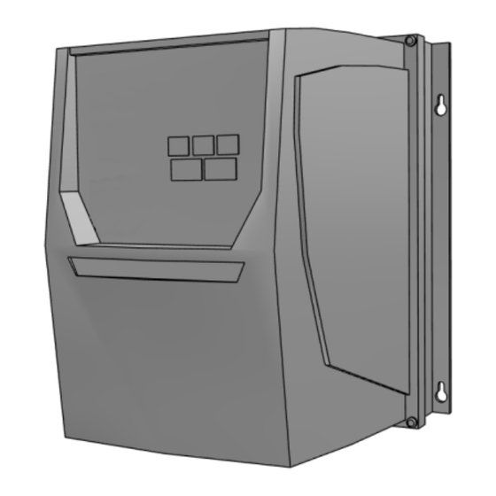
Included Items:
A. Controller Unit
B. Strain Relief Fitting
C. Pressure Transducer
D. Transducer Cable
E. Warranty Card
F . Installation Guide
G. Installation Manual
95 North Oak St. • Kendallville, IN 46755 • 1-800-345-9422
General Safety Information
Carefully read and follow all safety instructions in
this manual and on pump. Keep safety labels in good
condition. Replace missing or damaged safety labels.
This is a SAFETY ALERT SYMBOL. When you see
this symbol on the pump or in the manual, look for one of
the following signal words and be alert to the potential for
personal injury or property damage.
Warns of hazards that WILL cause serious
personal injury, death or major property damage if ignored.
!
Warns of hazards that CAN cause serious
personal injury or death, if ignored.
Warns of hazards that MAY cause minor
personal injury, product or property damage if ignored.
IMPORTANT: Indicates factors concerned with operation,
installation, assembly or maintenance which could result in
damage to the machine or equipment if ignored.
NOTE: Indicates special instructions which are important but
are not related to hazards.
!
Read these warnings and instructions
carefully. Failure to follow could result in serious bodily
injury and/or property damage.
!
Capacitors inside the Artesian Drive
controller can still hold a lethal voltage even after power
has been removed. Allow 5 minutes for dangerous internal
voltage to discharge before opening the unit.
Do not use power factor correction
capacitors with the Artesian Drive. Damage will result to
both motor and drive.
!
be in accordance with National Electric Code
(NEC) and all applicable local codes and
ordinances. A licensed electrician should perform
installation.
1
Electrical installations shall
025203 C
Advertisement
Table of Contents

Subscribe to Our Youtube Channel
Summary of Contents for Flint & Walling Artesian Drive AD070059
- Page 1 Operating Instructions & Parts Manual Please read and save these instructions. Read carefully before attempting to assemble, install, operate or maintain the product described. Protect yourself and others by observing all safety information. Failure to comply with instructions could result in personal injury and/or property damage! Retain instructions for future reference.
-
Page 2: How It Works
Be sure system is connected Pressure to a circuit equipped with a fuse or circuit Relief Valve Tank breaker of the correct rating. Inlet Motor Pump Always disconnect power source before performing any work on or near Outlet the controller, motor or its connected load. If the power disconnect point is out-of-sight, lock it in the open Transducer Power... -
Page 3: Before Getting Started
the system, the drive will protect the system and display a code for the fault. If possible, the drive will try to restart itself Do not use motor or system in swimming when the fault condition passes. areas. PUMP SIZING – ARTESIAN DRIVE (CENTRIFUGAL) IMPORTANT: This equipment should be installed by technically qualified personnel. - Page 4 2 In Minimum 2 In Minimum 6 In Minimum Pressure Pressure Transducer Relief Valve Leads Tank Inlet Motor Pump Outlet Pressure Tank to Pressure Transducer 6 In Minimum Power To Motor Mounting Clearance Power Supply IL2198 From Circuit Breaker Figure 3a - Mounting Clearance - Case Style 1 2 In Minimum 2 In Minimum 7.8 In Minimum...
-
Page 5: Pressure Tank
CIRCUIT BREAKER AND WIRE SIZING TABLE 3: PRESSURE TANK AIR PRECHARGE (PSI) The minimum circuit breaker size and maximum allowable System Pressure Pressure Tank Precharge wire lengths for connection of motor to the Artesian Drive are (at Transducer) Setting (± 2 PSI) given in the following table: TABLE 1: MINIMUM BREAKER SIZE AND MAXIMUM CABLE LENGTH (IN FEET) -
Page 6: Wiring Connections
Note: For correct motor rotation and pump performance on TABLE 4: DIMENSIONS F&W manufactured motors, leads 1-7, 2-8 & 3-9 on the motor Drive Model Case Style should be connected to U, V & W respectively. Three phase AD070059, motors from other manufactures may require that connection AD096074, 7-7/8”... -
Page 7: Start-Up And Operation
Start-Up and Operation While running the drive display shows the output frequency in Hz as well as motor amp draw and power use in kW. (Pressing and releasing the OK button toggles the large display area between the three measurements). When the drive is in standby the screen displays STOP . - Page 8 DRIVE CONFIGURATION Pressing and holding the OK button on the drive for OK button to accept the new value. Pressing and holding the approximately 3 seconds, will open the parameter menu OK button on the drive for approximately 3 seconds to return access to the drive.
- Page 9 TABLE 6: FACTORY DEFAULT SETTINGS PARAMETER RANGE P0-09 PID1 Feedback 1 0-100 % (Read Only) P0-12 Output torque 0-100 % (Read Only) P0-13 Trip Log (Read Only) P0-33 t-Run since Trip d:hh:mm (Read Only) P1-08 Motor rated current Drive Dependent 5.9 A 7.4 A 9.8 A 14.5 A 21.0 A 14.5 A 21.0 A 28.0 A 41.0 A...
- Page 10 DIAGNOSTIC FAULT CODES codes and the recommended corrective action for each are listed in the following chart. Should an application or system problem occur, built-in diagnostics will protect the system. The display will change Do not attempt to carry out internal to indicate the nature of the fault.
- Page 11 TABLE 8: ARTESIAN DRIVE EATON TROUBLESHOOTING GUIDE SYMPTOM POSSIBLE CAUSE CORRECTIVE ACTION Reverse rotation of motor with Motor/Pump is running backwards. parameter P4-13 Water flow rate is not as high as expected Pump capacity cannot supply the Use pump with higher flow rating (if demand.
- Page 12 95 North Oak St. • Kendallville, IN 46755 • 1-800-345-9422...
Need help?
Do you have a question about the Artesian Drive AD070059 and is the answer not in the manual?
Questions and answers