
Subscribe to Our Youtube Channel
Related Manuals for TransTel Communications IP 39-4 Series


Summary of Contents for TransTel Communications IP 39-4 Series
- Page 1 User Manual Installation and Programming Door Access Control VoIP Interface IP39-40PC IP39-41PC IP Door Phones IP 39-4X Series IP39-40AC IP39-41AC www.transtelcommunications.com...
- Page 2 Notification Notification is hereby given that TransTel Communications Inc. reserves the right to modify, change, update or revise this document from time to time as required without the prior obligation to notify any person, company or organization. Further, TransTel Communications Inc. makes no warranty or representation, either express or implied, with respect to merchantability, or fitness of its products for a particular purpose.
-
Page 3: Table Of Contents
Table of Contents Introduction ................................1 List of Available Models ..........................2 Product Overview ..............................3 IP Door Phone Package Content .......................... 4 IP Door Phone Front Panel ..........................5 IP Door Phone Main Functionality ........................6 Installation................................7 Mounting ..............................7 Connections ............................... - Page 4 7.8.1 Save Configuration File / IP Door Phone Backup .................. 35 7.8.2 Restore Configuration .......................... 36 7.8.3 Firmware Update ..........................37 7.8.4 Firmware Local Update ........................40 7.8.5 Set to Default ............................41 7.8.6 Restart / Cold Reset ..........................41 7.8.7 Web-Management Credentials ......................
-
Page 5: Introduction
1 Introduction The TransTel IP39-4X Series IP Door Phones offer a wide range of options for both indoor / outdoor access control and door entry options, based on industry standard SIP protocol. The TransTel IP Door Phones are standalone SIP phones, which enhance the functionality of a VoIP network by providing entrance door connectivity, access control, video monitoring, day and night call routing options and more. -
Page 6: List Of Available Models
List of Available Models Model Description IP39-40PC IP Door Phone, Piezo Keypad, Integrated Internal Video Camera IP39-40P IP Door Phone, Piezo Keypad IP39-41PC IP Door Phone, Piezo Single Button, Integrated Internal Video Camera IP39-41P IP Door Phone, Piezo Single Button IP39-40AC IP Door Phone, Touch Keypad, Integrated Internal Video Camera IP39-40A... -
Page 7: Product Overview
2 Product Overview TransTel IP IP394X Door Phones are smart, surface mounted access control devices connected to an IP network allowing door entry control and monitoring. They are designed for both indoor and outdoor use and are constructed in an aluminum case with piezo and touch keypads. The TransTel IP Keypad (IP39-40 Series) and Single Button (IP-39-41 Series) versions support the following features: Single Keypad... -
Page 8: Ip Door Phone Package Content
3 IP Door Phone Package Content “What’s In The Box” IP Door phone unit Metal rear cover Rear rubber gasket Set of connectors Hex key wrench for security screw Note: 1. If POE equipment is not available it is possible to use an External Power Supply (not supplied). External Power Supply shall be: ... -
Page 9: Ip Door Phone Front Panel
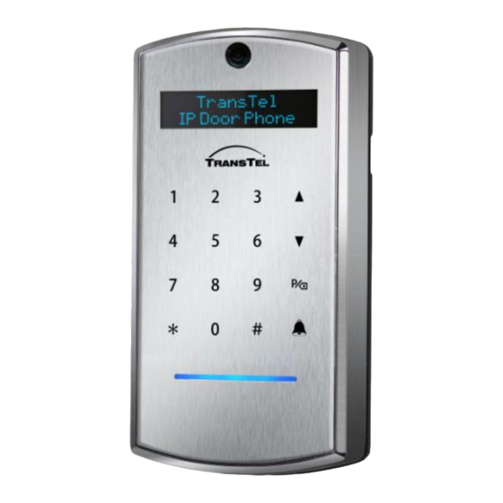
4 IP Door Phone Front Panel Figure 4-1 The IP Door Phone Unit Front Panel ▲▼ – scroll a speed dial directory. – enter the programming mode or use as a “Backspace” – Call predefined day/night extensions/ numbers and hang up a call. www.transtelcommunications.com... -
Page 10: Ip Door Phone Main Functionality
5 IP Door Phone Main Functionality The IP Door Phone unit can be integrated with an IP PBX (Server / SIP-Proxy) as a SIP extension. IP Door Phone can be connected to an IP PBX directly or via IP router, HUB or Switch. ... -
Page 11: Installation
6 Installation 6.1 Mounting The Door phone shall be mounted on the wall using rear metal cover and rubber gasket provided with the unit. 1. Unscrew the (hex) secret screw on the bottom part of the unit using the allen key provided. 2. -
Page 12: Connections
6.2 Connections For safety precautions and to avoid electrical damage to the unit any Power source like an external power supply or POE shall be disconnected during installation process. The External Power Supply is not included in the standard IP39-4X package 1. - Page 13 Figure 6-2 The IP Door Phone PCB Module Attention: The internal relay maximum supported current is 2A Important: To set the device in operational mode, switch 1 on PCB shall be switched to position “Normal”. PCB elements Description 1 ( SW2) Factory Default Settings switch: ‘Normal’...
- Page 14 PCB elements Description Microphone Connector Speaker Connector 6- Ethernet POE/LAN connection 5VD (5V DC) External power supply 5VDC 2A input (if no POE applied). Draw attention on connection polarity: +5V and GND marked on PCB (Figure 6-2) The External Power Supply is not included in the standard IP394X package SEN 1/2 (Sensor 1/2*) Door status detector.
-
Page 15: Reset Device To Factory Default Configuration
Figure 6-3 IP394X Connections Diagram with External Switch Button Note: The door electrical Lock requires separate powering follow by door lock manufacture’s requirements 6.3 Reset Device to Factory Default Configuration IP Door phone can be reset to its Factory default configuration by using the following actions: 1. - Page 16 Figure 6-4 Factory Default Settings Switch SW2 www.transtelcommunications.com...
-
Page 17: Programming
7 Programming Access to Web Management Interface The programming application can be launched from a web browser. To run the application type in address bar the IP Door phone IP address. The Web Management Application Login screen appears: Figure 7-1 The WEB Programming Interface Login Screen IP 39-4X provides different management levels for WEB-Management: Administrator and User ... -
Page 18: Home Screen
7.2 Home Screen Figure 7-2 The IP Door Phone Web-Management Application Main Screen The left side navigation menu contains the following items: Parameter Description Network LAN Configuration parameters HTTPS Configuration SIP Account settings SIP Advanced settings Audio – SIP audio codec configuration Video –... - Page 19 The Home page parameters table includes following information: Parameter Description Model Name IP Door Phone Product name IP Door Phone Product ID – the manufacturer identification code Model Number Software Version No. Installed firmware release identification code Firmware’s release date Software Version Date MAC Address IP Door Phone MAC Address...
-
Page 20: Network Parameters
7.3 Network Parameters 7.3.1 Network Configuration Parameters Figure 7-3 Network -> LAN Screen Note: At least the ‘DNS Server-1’ parameter shall be specified in ‘Static’ IP address configuration mode. Parameter Description IP Address Acquire Available options: Static DHCP Static mode allows to specify Network parameters manually. -
Page 21: Network / Nat Traversal
7.3.2 Network / NAT Traversal These settings are relevant only if the IP Door phone is part of a LAN and has an internal (not public) IP address. NAT Traversal function allows traffic to get to the specified destination when a device does not have a public IP address. -
Page 22: Network -> Https Activation
7.3.3 Network -> HTTPS Activation The HTTPS Activation parameter will require the HTTPS secure protocol for the web management communication. HTTPS provides authentication of the web-management server that one is communicating with, which protects against man-in-the-middle attacks. Additionally, it provides bidirectional encryption of communications between administrator’s PC and the IP Door Phone. -
Page 23: Auto Provision
7.3.4 Auto Provision Auto provision screen allows to configure APS (Auto Provisioning Server) server IP address / DNS name and IP Door Phone configuration file name. Figure 7-6 Auto-Provisioning Screen Parameter Description Server Type Available options: HTTP HTTPS Specify the connection type with APS server User Name The user name which shall be to be used for APS server identification... -
Page 24: Sip Parameters
SIP Parameters 7.4.1 SIP Account Screen Figure 7-7 SIP Account Configuration Screen Parameter Description Username The SIP account user name which shall be to be used for SIP extension identification Auth User ID The SIP account user name which shall be to be used for SIP extension registration in SIP proxy Password The SIP extension authorization password for registration in SIP proxy. -
Page 25: Sip Audio Codecs
7.4.3 SIP Audio Codecs Figure 7-9 SIP Audio Codecs Screen This screen specifies Audio codecs which are used in SIP protocol codec’s priority. Available following codecs: PCMU – G.711µ-low PCMA – G.711 a-low Speex 32 / 16 / 8 KHz ... -
Page 26: Sip Advanced Settings
7.4.5 SIP Advanced Settings Figure 7-11 SIP Advanced Settings Parameter Description SIP Reg Expires Set the minimum time for IP Door Phone SIP extension registration attempts. DTMF Mode This option defines how DTMF signaling can be presented or recognized in SIP traffic. Note: Requires the opponent side configuration as well Available Options: ... -
Page 27: Telephony
Telephony 7.5.1 Telephony Parameters Figure7-12 Telephony Parameters Screen Parameter Description Auto Answer Available options: Disable Enable This parameter Enables / Disables the IP door phone to auto pick up incoming calls Specifies ‘#’ sign typed on the IP Door phone keypad as end of dialing Digit # as End of dialing direct destination number Inter-digit Timeout... -
Page 28: Day And Night Settings
7.5.2 Day and Night Settings Note: The Single button Door Phone allows Day and Night destination dialing. Speed Dial Destination dialing is relevant for IP39-40 Series Only (Keypad Housing) edition only. Figure 7-13 Telephony Day & Night Settings Screen Parameter Description Switch Mode Available options:... -
Page 29: Speed Dial And System Subscribers Table
7.5.3 Speed Dial and System Subscribers Table Note: Speed Dial Destination dialing is relevant for Keypad Housing edition only. Single button Door Phone allows Day and Night destination dialing. The IP Door phone provides an option to create up to 99 System subscribers. Each system subscriber can be identified by its SPD number (Speed Dialing Code) and includes a set of destination telephony numbers where a subscriber can be reached when an appropriate SPD code is dialed from the IP Door phone keypad. -
Page 30: Door Functions
No Answer Forward Destination Specifies telephony number where the IP Door phone outgoing call will be forwarded in case ‘Day’ or ‘Night’ destinations do not answer Door 1 Opening Code Specifies the Door opening code, which opens a door remotely when dialed from destination number during conversation with the IP Door Phone. -
Page 31: Door Access Codes
7.6.2 Door Access Codes Figure 7-16 Door Access Codes Screen IP Door phone supports up to 9 Door access codes. The different Door access code can be specified separately for Door 1(Relay 1) and Door 2 (Relay 2) Parameter Description Access Code 1~9 Specifies the Door opening code, which opens a door when typed on the IP Door phone keypad in ‘Stand by’... -
Page 32: Sensor
Dial Door opening prefix and follow the door opening code: for example: If a Code prefix selected as ‘*’ and door opening code is ‘4321’, so need to dial *4321 in order to open a door. LED Display with masked Door Opening code 7.6.3 Sensor Figure 7-17 Door Sensors and External Switch Button Configuration Screen... -
Page 33: Sensor Door Status Control
The Door ‘Status Sensor’ provides an option to control the doors open/close status and activates alarm calls when the door does not return to its IDLE mode during specific time interval The ‘External Switch Button’ provides an option to open a door manually. See Figure 6-2 7.6.3.1 Sensor Door Status Control Door Sensors control the door opening status and send an alarm call to preconfigured Day / Night destination if the door opening time (‘Door Opened Timeout’... - Page 34 Figure 7-20 Door Sensors Connection The ‘Door Opened Timeout’ parameter controls the maximum allowed time when door can be open. Parameter can be configured by using the WEB interface: Door Functions / Parameters screen (See Figure 7-15). Door Phone initiates alarm call to pre-configured Day or Night destination number if a ‘Door Opened Timeout’...
-
Page 35: System Parameters
System Parameters 7.7.1 Volumes Volumes screen allows to adjust the IP Door Phone’s internal microphone and speaker volumes. Figure 7-21 System Volume’s Settings Screen Parameter Description Microphone Volume This parameter is to adjust the microphone volume Speaker Volume This parameter is to adjust the speaker volume ‘Apply’... - Page 36 Time Zone The local time zone Activates the ‘Daylight Saving Time’ (DST) support. Automatically corrects Daylight Saving Time the system clock when enabled and configured Daylight Saving Time Start / End Specifies days to correct the Door Phone system clock in accordance with the local DST rules, where: MM –...
-
Page 37: Camera
7.7.3 Camera Figure 7-23 Camera Configuration Screen ‘Camera’ screen allows adjusting the internal video camera parameters: Allows to adjust the internal video camera ‘Brightness’. Allows to set Brightness selected parameter in interval: -2 / +2 *. Resolution Allows to select the internal video camera resolution mode: Normal: 640 x 480 High: 720p Note:... -
Page 38: Lcd Display Settings
7.7.4 LCD Display Settings Figure 7-24 The LED Display Configuration Screen The IP Door Phone front panel LCD Display can be configured to indicate text messages or dialing instructions for guests and users. Parameter Description Show Message Available options: Enable ... -
Page 39: Administration Parameters
Administration Parameters 7.8.1 Save Configuration File / IP Door Phone Backup Figure 7-25 Save IP Door Phone Configuration File Screen This screen allows back up of the IP Door configuration by using the TFTP protocol. Note: 1. The TFTP server can be installed and activated by using Third Party Company tftp software. For example: Tftpd32 application, which can be found on the following URL: http://www.snapfiles.com/download/dlTftpd32.html 2. -
Page 40: Restore Configuration
Press ‘Apply Now’ button tftpd32 software screen indicates the Configuration file transfer status When operation is done the ‘config.cfg’ file can be found in the storage directory 7.8.2 Restore Configuration Figure 7-26 IP Door Phone Restore Configuration Screen www.transtelcommunications.com... -
Page 41: Firmware Update
Parameter Description TFTP Server IP address Specifies the TFTP server on a TCP/IP network, where configuration files was previously stored. ‘Apply Now’ button This button shall be used in order to initiate the restore process. To restore configuration file requires exactly the same procedures as in the previous chapter. 7.8.3 Firmware Update Figure 7-27 Update Firmware Screen... - Page 42 IP Address The IP Address of the PC where the TFTP server software is located FTP Server Login Name Specifies the FTP server account login name. Password Specifies the FTP server account password name. IP Address Specifies the FTP server IP address Update file The firmware file name.
- Page 43 Go to IP394X Web Management Admin/ Update screen and fill ‘Update File’ and TFTP Server / IP Address fields following the actual configuration where: o Update File – The IP394X Firmware file name; ‘ ip-394X-wXXXNN.tar.gz ‘ where XXXNN – firmware release number + edition number.
-
Page 44: Firmware Local Update
7.8.4 Firmware Local Update The IP Door Phone internal Firmware can be updated during the WEB-Management session directly from the IP Door Phone management GUI. To update the Firmware directly from the Web-Management screen: Select ‘Update Local’ option from the ‘Admin’- left navigation menu Figure 7-28 ‘Admin’... -
Page 45: Set To Default
Note: 1. The Firmware update procedure takes at least 2 minutes. Do not disconnect power from the unit when Firmware update procedure runs 2. WEB-Management screen shows message ‘Please wait, Door-phone is still processing Prepare Update!’. Use your web-browser refresh in order to refresh a screen and re-connect with the unit 3. -
Page 46: Web-Management Credentials
7.8.7 Web-Management Credentials IP 394X provides different management levels for WEB-Management: Administrator and User ‘Administrator’ level has access to all IP394X configuration parameters ‘User’ level has limited access to IP394X configuration parameters. Note: 1. The ‘Administrator’ management level web-login name is ‘admin’ 2. -
Page 47: Syslog Server Settings
This screen allows changing the Web-Management User login password. To change a password: Type existing password in ‘Original Password’ field Type new password in ‘New Password’ field Confirm New Password by typing the New Password in ‘Confirm’ field ... -
Page 48: Ping Test
detail than in ‘TRACE’ mode Log Details Specifies and enables the data output in Syslog event messages Day Name – Print the Day of the Week Name Year – Print the event Year Month – Print the event Month Day – Print the event Date Time –... - Page 49 After a few seconds, Ping results will be shown on the screen. www.transtelcommunications.com...
-
Page 50: User Operations
8 User Operations Note: 1. IP Door Phone features / capabilities are based on programming set up and configuration 2. Pressing the ‘Ring/Call’ button a second time performs the “Call Cancellation” function. Parameter Description See Chapter 7.6.2 (Opening Code) Access by using the “Door Access Code” See Chapter 8.1 (Operations) See Chapter 7.6.2 (Opening Code) Access by using “Ring Button”... -
Page 51: Door Opening By Using The External Switch Button
Door Opening by Using the External Switch Button The Door phone supports an external switch button installation. The separate external button can be used for each door lock. This allows the door opening with a hardwired switch button. An external button should be connected to the Sensor-1 and Sensor-2 terminals. -
Page 52: Peer-To-Peer Calls
To dial the Operator: Press the button Door phone dials to a preconfigured destination number, depending on the Operational mode: Day or Night Note: 1. Day and Night operational modes can be switched manually via Web-Management interface or automatically (See Chapter 7.5.2) 2. -
Page 53: Dialing By Using Speed Dial Destinations
Dialing by Using Speed Dial Destinations The IP Door Phone supports up to 99 Speed Dialing System subscriber destinations (See Chapter 7.5.3), where each system subscriber includes following telephony destinations: ‘Day Time destination’ – the number which will be dialed in the Day operational mode ... -
Page 54: Speed Dialing Using The Spd Code
8.6.1 Speed Dialing Using the SPD Code For speed dial System subscriber’s destination number by using the Speed dialing SPD code: Type known SPD code on the IP Door phone keypad Press ’Ring/Call’ button Door phone dials to pre-configured destination number Figure 8-3 IP Door Phone Keypad 8.6.2 Speed Dialing by Using the LED Display Search... -
Page 55: Setting The Maximum Conversation Time
Door Release Mechanism SIP Extension Figure 8-4 Door Opening from Remote Extension during Conversation Note: ‘5’ The default Extension’s Door opening code 1 for Relay number 1 is , the rest of codes shall be configured via Web-GUI / Door Access Codes screen (See Chapter 7.6.2) Setting the Maximum Conversation Time The IP Door phone controls the conversation time duration. -
Page 56: Case Opening Alarm
Case Opening Alarm Note: 1. Feature works automatically and doesn’t require specific configuration 2. LED Display shows message ‘Destination is not set’ in case when unit housing is open during start up and Day/Night destination is not configured. The IP Door phone initializes a call to Day / Night destination in case of housing opening. Figure 8-5 Case Opening Alarm Call 8.10 Door Opening Report in the Syslog Server... - Page 57 Figure 8-6 Syslog Server Settings Screen Enter IP address in ‘Syslog Server IP Address’ field The rest of selections are default and shown on Figure 8-6. Click ‘Save’ button and follow Save& Reboot option from Navigation menu ...
- Page 58 From this moment only filtered messages which includes door opening codes will be printed in Syslog server Figure 8-8 Syslog Server Screen with Filtered Messages www.transtelcommunications.com...
-
Page 59: Technical Specification
9 Technical Specification Power Supply 5V DC; 1.5A or Power Over Ethernet IEEE 802.3af compliant Communication Interface Ethernet for voice; and for programming DC Leakage <10 µA Imbalance Ratio 300-3400Hz > 46dB Return Loss 300-3400Hz > 18dB Relay’s Switching Current 30VDC - 2A Max VoIP Protocol Supported SIP;... - Page 60 www.transtelcommunications.com...
Need help?
Do you have a question about the IP 39-4 Series and is the answer not in the manual?
Questions and answers