
Summary of Contents for DTV INNOVATIONS Falcon HMR5442
- Page 1 Multi-Format Receiver Model Falcon HMR5442 Operations Guide Rev. D.1 June 17, 2016...
- Page 2 DTV INNOVATIONS makes no warranties expressed or implied as to non-infringement of third party rights, or fitness for any particular purpose. In no event will DTV INNOVATIONS be liable to any customer, user or third party for any consequential or incidental damages, including lost profits or lost savings, or for any claim by any party due to the use of its products.
-
Page 3: Overview
Introduction Revision History Overview The Falcon HMR5442 Operations Guide is updated periodically to reflect new system capabilities, provide more information, and to correct errors. Revision Date Description June / 03 / 2013 Initial Release May / 30 / 2014 AC3 interoperability; SMTE-302M pass through;... - Page 4 Falcon HMR5442 Multi-Format Receiver Page | 4...
-
Page 5: Cautions And Warnings
Introduction Safety Summary Cautions and Warnings The following symbols identify situations in which you should exercise caution to prevent injury or damage to the unit. This symbol indicates actions that could be harmful to you or to the unit. This symbol indicates potentially lethal voltages. Safety Precautions Equipment must be installed by a qualified service person and a permanent earth connection to the secondary earthing terminal is essential before... - Page 6 Ensure that all cables and cords are concealed. Failure to do so may result in personal injury or serious damage to the unit. Avoid exposing the unit to water and moisture — Contact DTV Innovations’ Customer Support department if the unit is exposed to any liquid. Serious damage could occur to the unit’s components if exposed to liquid.
- Page 7 Introduction Double pole/neutral fusing — The power supply has two fuses and might have live circuits even when one fuse has blown. Risk of Explosion if Battery is replaced by an Incorrect Type. Dispose of Used Batteries According to the Instructions. This unit contains application specific hardware and software.
- Page 8 Opening or removing covers may expose you to dangerous voltages or other hazards as well as void your warranty. Contact DTV Innovations support department to obtain qualified support. Call for support if the following occur: ...
-
Page 9: Weee Disposal Instructions
Introduction WEEE Disposal Instructions Disposal Instructions Do not dispose of this device with unsorted household waste. Improper disposal may be harmful to the environment and human health. Please refer to your local waste authority for information on return and collection systems in your area. -
Page 10: Table Of Contents
Falcon HMR5442 Multi-Format Receiver Figures/Tables Figure 2- 1 Rear Panel..........................19 Figure 4- 1 Home Page..........................49 Figure 4- 2 Import/Export Quickset......................50 Figure 4- 3 Manage Configuration......................51 Figure 4- 4 View Configuration........................52 Figure 4- 5 Import/Export Configuration....................53 Figure 4- 6 Transport over IP Page......................54 Figure 4- 7 BISS Decryption........................55... - Page 11 Introduction Contents Overview............................... 3 Cautions and Warnings..........................5 Safety Precautions............................5 WEEE Disposal Instructions........................9 System Overview & Installation......................13 Overview..............................13 Features..............................14 Audio..............................15 Demodulator............................15 ASI input and Output..........................15 Monitor and Control Functions......................15 Front Panel..............................15 Remote Control............................16 Programmable Memory..........................16 Configuration Sets..........................
- Page 12 Falcon HMR5442 Multi-Format Receiver Configuration Sets............................43 Restoring a Default Factory Configuration.................... 43 Saving User Configuration and Renaming..................... 43 Saving a User Configuration Under an Existing Label................44 Deleting a User Configuration Label......................44 Loading User Configuration Label......................44 Front Panel Lock/Unlock......................... 44 Locking the Front Panel..........................44...
-
Page 13: System Overview & Installation
Audio support for all popular AAC codecs is included as well. The Falcon HMR5442 is a rugged, compact Audio & Video receiving and decoding system designed for a wide variety of MPEG-4 & MPEG-2 applications. The small size and multitude of features make this a perfect receiver / decoder for portable applications while providing a host of features suitable for the most demanding distribution and laboratory uses. -
Page 14: Features
Auto-ranging, auto-sensing 90-240 VAC power supply Rugged chassis construction The Falcon HMR5442 has a powerful video decoding engine to allow for decoding of all of the below formats: Standard Definition Video o MPEG-2 4:2:0 Main Profile @ Main Level (1 to 15 Mbps) o MPEG-4 Part 10 (AVC) Main Profile @ Level 3.0 (0.1 to 10 Mbps) -
Page 15: Audio
Full Embedded Web Browser control. Front Panel The Falcon HMR5442 front panel interface allows you to scroll through a standard set of menus to easily set your operating parameters. All configuration and monitoring functions can be efficiently performed using the front panel. -
Page 16: Remote Control
The Falcon HMR5442 maintains the last user configuration in flash memory. Configuration Sets The falcon HMR5442 has a number of default configurations that can be restored as well as numerous user-defined configuration sets that can be saved and restored. Construction The Falcon HMR5442 is a rugged, 1 RU high (4.5 cm), 19”... -
Page 17: Installation
Overview & Installation Installation The unit can be installed on a tabletop or in a rack. Rack Installation If the equipment is going to be installed permanently, install the unit in a rack using the rack mount brackets. Ventilation The unit must be positioned to receive adequate ventilation at all times. The cooling fan pulls air in through the side vents to the right and exhausts it out the side vents on the left. - Page 18 To power up the unit, press the power switch to the On, or 1 position. The power- on cycle takes approximately 30 seconds, as the unit performs extensive self- diagnostics in this time period. During the powered- up cycle, the unit displays ‘Falcon HMR5442 Various other MPEG2/MPEG4 HD/SD Decoder Initializing...’.
-
Page 19: Figure 2- 1 Rear Panel
2. Rear Panel Rear Panel Connections All Falcon HMR5442 external connections are located on the rear panel, as shown in the following picture. Split View: Left and Right side respectively: Figure 2- 1 Rear Panel Page | 19... - Page 20 Falcon HMR5442 Multi-Format Receiver Figure Label Back Panel Connector Type Description Label RF Input A RF INPUT A F (75Ω) L-Band IF 950 to 2150 RF Input B RF INPUT B F (75Ω) L-Band IF 950 to 2150 Analog Audio Output...
-
Page 21: Network Interface
The remote port is configured as a DTE on a DB-9 male connector. To connect a remote unit to the Falcon HMR5442 through the RS-232 control port, a cable is needed that is the appropriate length for the application. Because the Falcon HMR5442 is a DTE device, a NULL modem cable or adapter is required to connect to it. -
Page 22: Rf Input
Falcon HMR5442 Multi-Format Receiver Signal Direction Definition Input Data Carrier Detect Input Receive Data Output Transmit Data Output Data Terminal Ready Ground Input Data Set Ready Output Ready to Send Input Clear to Send Input Ring Indicator Table 2-3: Remote Port Pin Assignments RF Input The unit provides 2 RF Input ports on female F connectors with 75Ω... -
Page 23: Asi Input
Rear Panel -DATA OUT Sync -DVLD Sync -422_CTS Async Unused Unused 232_RTS Async Table 2-4: Auxiliary Data Port Pin Assignments ASI Input The ASI Input accepts the incoming ASI transport stream with data rates up to 213 Mbps. It is a female BNC connector with 75Ω impedance. Video Output The unit provides connections for both analog and digital SD/HD video. -
Page 24: Asi Out
Falcon HMR5442 Multi-Format Receiver Signal Pin 1 TMDS Data2+ Pin 2 TMDS Data2 Shield Pin 3 TMDS Data2− Pin 4 TMDS Data1+ Pin 5 TMDS Data1 Shield Pin 6 TMDS Data1− Pin 7 TMDS Data0+ Pin 8 TMDS Data0 Shield Pin 9 TMDS Data0−... - Page 25 Rear Panel The unit provides 4 digital AES/EBU audio output port using DB-9 pin female. A DB9 to BNC cable adapter is available. Signal Definition AES/EBU A AES/EBU B AES/EBU C AES/EBU D Unused Ground Shield A Ground Shield B Ground Shield C Ground Shield D Table 2-6: Digital Audio Port Pin Assignments...
-
Page 26: Fault Relay
Falcon HMR5442 Multi-Format Receiver Fault Relay The Fault Relay output is support with an RJ-11connector and is used to communicate the state of the unit in a redundant configuration. A downstream redundancy switch monitors the state of each decoder using this Fault Relay. If the active decoder faults, the redundant partner’s output is used. -
Page 27: Front Panel Management
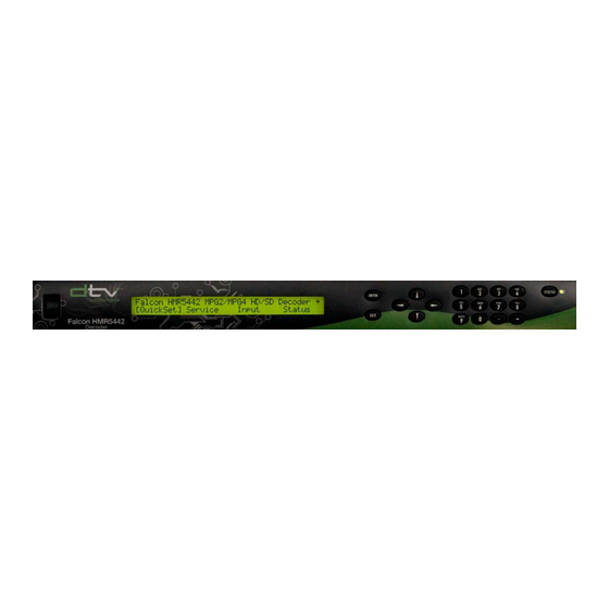
3. Front Panel Management Front Panel Components The front panel enables you to easily and efficiently configure and monitor the unit. Figure 3-1: Front Panel The front panel consists of the following components: Front Panel Component Used to… LCD (Liquid Crystal Display) Display menus, parameters, information, and messages. -
Page 28: Navigating Through Front Panel Menus
Falcon HMR5442 Multi-Format Receiver Navigating Through Front Panel Menus The front panel LCD display and buttons were designed to maximize speed and efficiency of navigation through the menu structure. LCD Display The flowing figure shows a sample menu on the front panel:... -
Page 29: Types Of Menus
Front Panel Types of Menus All menus are displayed in the following format: HMR5442 / Service → [Select] Audio Video The first line identifies the current menu level. This example shows the Service menu. The arrow, when displayed, indicates that there are additional menu options available at that level. - Page 30 Falcon HMR5442 Multi-Format Receiver Alphabetic Entries The first press of a number key displays the first character in the set; sequential presses of the same key advance through the character set, in a circular fashion. The cursor is advanced by either pressing another number key, or by pressing the right arrow key. For...
-
Page 31: Status Button
While the HMR5442 is setting the parameter to the new value, the front panel is temporarily disabled. When the Falcon HMR5442 configuration is changed using the front panel, the changes are automatically stored in non-volatile memory. The Falcon HMR5442 automatically restores to the saved configuration whenever the unit is reset or powered up. -
Page 32: Correcting Mistakes
Exit button which returns you to the previous menu level. Left or Right buttons which take you to the next parameter. In either situation, the Falcon HMR5442 will ignore any values entered and return the parameter to its original setting. After Pressing the Enter Button... -
Page 33: Front Panel Menu Summary
HMR5442/Input/RF/RF A7/8 > LO Frequency = 10750 Front Panel Menu Summary The following table lists detailed descriptions of the Falcon HMR5442 front panel commands. The commands are organized in the order in which they appear on the front panel. Included are: ... - Page 34 /Menu configurations sets, management of the user-defined list, and then re-initialize the Falcon HMR5442 using either the user-defined configuration sets or predefined factory default configuration settings. These configuration sets are not altered by reset, power cycling, of the decoder. Power cycle is recommended after each configuration load.
- Page 35 Front Panel Front Panel Menu Function Options/Response Format Preferred None Default: None; If a language in the service Language English matches the preferred language, that audio is Chinese selected. If none of the audio channels in the selected service are in the preferred language, the Danish Dutch unit selects the first audio channel detected in the...
- Page 36 Falcon HMR5442 Multi-Format Receiver Front Panel Menu Function Options/Response Format Delay -33 to 300 msec Sets the delay between the time the video data is Default: 0 (zero) received and the time the video data is sent to the video output port (lip sync).
- Page 37 PGCA PGCA Auth A read only status of whether the unit is currently authorized to receive a PGCA transmission. HMR5442/Input/Sel Used to Select the Falcon HMR5442 Input sources (ASI, RF-A, RF-B). Input Source Select input source RF-A RF-B Select ASI, RF-A, RF-B or IP (if installed) Select the RF port (RF A –...
- Page 38 Falcon HMR5442 Multi-Format Receiver Front Panel Menu Function Options/Response Format LNB Voltage Sets LNB voltage. Acquisition Range Sets acquisition range control mode. Auto – the unit will set the acquisition range, in Control (IDC DVBS2 most cases to half the symbol range (see customer and on board demods release notes for more detail).
- Page 39 IP daughter card to the latest firmware Command: 1234 within the unit. HMR5442/Status Falcon HMR5442 Fault Reporting and Monitoring. Current Displays a list of current operational faults. Up and down arrows scrolls through each fault listed. Upper right corner of display will shows two numbers separated by a slash (/).
- Page 40 Falcon HMR5442 Multi-Format Receiver Front Panel Menu Function Options/Response Format HMR5442/Admin Communication setup for the 9-pin serial connector. /Serial Baud Rate Selects the asynchronous interface baud rate for 1200 the remote port. 2400 4800 9600 19200 38400 (default) 57600 115200...
- Page 41 Enables the Genlock feature. HMR5442/Reset Warm boot reset selection. Press ENTER to Reset, EXIT to Cancel HMR5442/Version Software Version Queries the version of firmware currently in use on the Falcon HMR5442. Serial number Displays the Falcon HMR5442 serial number. Page | 41...
- Page 42 Falcon HMR5442 Multi-Format Receiver Front Panel Menu Function Options/Response Format Demod Version Displays the Demod vesrion. IP FPGA Version Displays the IP FPGA version number. IP CPLD Version Displays the IP CPLD version number. FPGA Version Displays the FPGA version number.
-
Page 43: Hmr5442 Procedures
Front Panel HMR5442 Procedures This section provides detailed steps for performing various Falcon HMR5442 tasks. Configuration Sets Restoring a Default Factory Configuration To restore a default configuration: From the main menu, select [QuickSet]. The configuration menu appears. Select Default, The default restore menu displays. -
Page 44: Saving A User Configuration Under An Existing Label
Falcon HMR5442 Multi-Format Receiver Saving a User Configuration Under an Existing Label To save a user-defined configuration set under an existing label: Select QuickSet from the main menu. Select QuickSet/Save and using up and down arrows select User1…User16. Press Enter. -
Page 45: Date And Time
The front panel displays State = Unlocked indicating that the front panel is now unlocked. If the wrong password is entered, the Falcon HMR5442 displays Password = 0. If this occurs, use the front panel keypad to type in the correct password and press Enter. -
Page 46: System Reset
From the main menu, select the right arrow. Select Reset. Press the Enter key. The Falcon HMR5442 is reset to the last configuration set; all programmable logic and firmware is reloaded; the unit is restarted; and the fault history log is cleared. Page | 46... - Page 47 Front Panel Page | 47...
-
Page 48: Web Management
Connect an Ethernet cable to the Ethernet port on the back of your Falcon HMR5442. Power-on the Falcon HMR5442. From the front panel, set the IP address and subnet mask on your Falcon HMR5442. These should be set to be consistent with your network settings. -
Page 49: Figure 4- 1 Home Page
Web Management The following are example web pages from the browser command interface. Not all pages are shown. For those pages not shown, the menu structure is similar enough to the front panel command structure as to not merit inclusion. Home Page Home page view includes summary status information. -
Page 50: Figure 4- 2 Import/Export Quickset
Falcon HMR5442 Multi-Format Receiver Import Export Quickset This option allows the import or export of a file containing all of the configurables for one quickset in a user readable format. Figure 4- 2 Import/Export Quickset Page | 50... -
Page 51: Figure 4- 3 Manage Configuration
Figure 4- 3 Manage Configuration Note: In the view config menu, it is not possible to manually edit a configuration. In order to edit a configuration, the Falcon HMR5442 must be set to the required configuration and then that configuration must be saved. -
Page 52: Figure 4- 4 View Configuration
Note: Individual configurations may be imported from a file or exported to a file. These files have a human readable and a machine readable section. These configuration files may not be edited, as only the machine readable section is used by the Falcon HMR5442. The human readable sections are for information only. -
Page 53: Figure 4- 5 Import/Export Configuration
Web Management Import/Export a Clone File This option allows the export or import of a single file containing all of the configurables for a complete unit in a machine readable format only. Figure 4- 5 Import/Export Configuration Note: A clone file is a complete machine readable copy of the existing and all saved configurations. When contacting customer service, you should have a clone file ready. -
Page 54: Figure 4- 6 Transport Over Ip Page
Falcon HMR5442 Multi-Format Receiver Transport over IP Optional Transport over IP input interface network configuration page. Figure 4- 6 Transport over IP Page Page | 54... -
Page 55: Figure 4- 7 Biss Decryption
Web Management CA/Decryption Decryption configuration. Figure 4- 7 BISS Decryption Note: The BISS entries are not readable after entry. Page | 55... -
Page 56: Figure 4- 8 Video Page
Falcon HMR5442 Multi-Format Receiver Video This page is read only. Figure 4- 8 Video Page Note: The Video page provides a status summary of the presently received video format. Page | 56... -
Page 57: Figure 4- 9 Audio Page
Web Management Audio The Audio page summarizes all four audio output settings. Figure 4- 9 Audio Page Page | 57... -
Page 58: Figure 4- 10 Code Update
Falcon HMR5442 Multi-Format Receiver Code Update Note: code updates are performed through the web browser interface. Figure 4- 10 Code Update Page | 58... - Page 59 Web Management Page | 59...
-
Page 60: Admin
5. Admin Maintenance Falcon HMR5442 decoders require no periodic or preventive maintenance other than keeping the cooling fan intake grills free of any obstruction. Field Software Updates The unit is controlled by a built-in microcontroller equipped with a non-volatile memory that is used to store operational software, firmware, and configuration settings. -
Page 61: Licensing
Administration Licensing Falcon HMR5442 decoders can be purchased with optional software and hardware modules. The front panel admin menu can be used to view licensable features (variants). If you would like to add features to your unit, contact your sales representative. -
Page 62: Troubleshooting
6. Troubleshooting This chapter includes the following information: Fault reporting and monitoring, including the status LED and status button, viewing current faults, and viewing the fault history and fault relay logs. Initialization self-test diagnostic functions. Listing all individual faults. ... -
Page 63: Current Fault Log
Troubleshooting Current Fault Log Current faults are reported in real-time. This means that only conditions that are present at the time of the query are displayed, regardless of what fault conditions have existed in the past. A current fault exists when the Status LED is yellow. All current faults are recorded in the fault history log;... -
Page 64: Fault Summary
HMR5442 Multi-Format Receiver Fault Summary Most faults are non-critical, informational faults. When faults occur, perform the following steps: If the unit is functioning normally, clear the faults and continue operation. If the unit continues to fail: Reset the box to the defaults ... - Page 65 Troubleshooting No Audio: Check to see if you have a valid audio PID and that it is selected according to the audio port you have connected. If embedded, check to make sure you have the right channel pair. Go to [SERVICE][AUDIO]. ...
-
Page 66: Index
7. Index Network Interfaces........... 21 Alphanumeric Keypad..........30 Analog Audio Input..........25 ASI Output............... 24 Precautions, Safety.............6 Audio Inputs.............24 Rear Panel..............19 Cautions..............5 Revision History............3 Certification..............7 Clone the Setup....48, 49, 50, 51, 53, 54, 55, 56 Composite Video Input..........24 Safety Precautions............6 Digital Video Input..........
Need help?
Do you have a question about the Falcon HMR5442 and is the answer not in the manual?
Questions and answers