
Subscribe to Our Youtube Channel
Related Manuals for Cool-Living CL-12HA2


Summary of Contents for Cool-Living CL-12HA2
- Page 1 Mini Split Air Conditioner Instruction Manual Model: CL-12HA2, CL-18HA2, CL-24HA2 This manual includes crucial information and recommendations that we kindly request you to follow for optimal results with the air conditioner.
-
Page 2: Table Of Contents
CONTENTS SAFETY PRECAUTIONS PARTS REMOTE CONTROL OPERATING INSTRUCTIONS INSTALLATION PRECAUSTIONS INDOOR UNIT INSTALLATION OUTDOOR UNIT INSTALLATION TEST OPERATION MAINTENANCE TROUBLESHOOTING WARRANTY * The design and specifications are subject to change without prior notice for product improvement. Consult with the sales agency or manufacturer for details. * The shape and position of buttons and indicators may vary according to the model, but their functions are the same. -
Page 3: Safety Precautions
SAFETY PRECAUTIONS SAFETY RULES AND RECOMMENDATIONS FOR THE INSTALLER Read this guide before installing and using the appliance. Restrict children's access to the work area during the installation of indoor and outdoor units to prevent unforeseen accidents. Make sure that the base of the outdoor unit is firmly fixed. Check that air cannot enter the refrigerant system and check for refrigerant leaks when moving the air conditioner. - Page 4 SAFETY PRECAUTIONS SAFETY RULES AND RECOMMENDATIONS FOR THE INSTALLER 1. Do not try to install the conditioner alone; always contact specialized technical personnel. 2. Specialized technical personnel should conduct cleaning and maintenance tasks. Always disconnect the appliance from the mains electricity supply before initiating any cleaning or maintenance procedures.
- Page 5 SAFETY PRECAUTIONS SAFETY RULES AND PROHIBITIONS 1. Avoid bending, tugging, or compressing the power cord, as this may lead to damage. A damaged power cord can result in electrical shocks or fire. Only specialized technical personnel should replace a damaged power cord. 2.
-
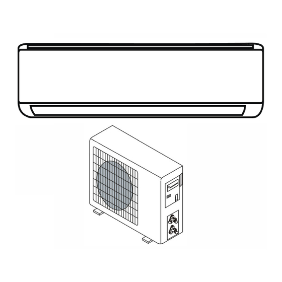
Page 6: Parts
PARTS Indoor Unit Mounting Plate Air Filter Air Inlet Front Panel Emergency Button Air Outlet Air deflector and Flap Refrigerant Connecting Pipe Outdoor Unit Air Inlet Wiring Cover Drainage Pipe Connection Wiring Valve Protective Cover Gas Valve (Low Pressure Valve) Liquid Valve (High Pressure Valve) With the protective cover removed. - Page 7 PARTS Indoor Display Function Indicator for Timer, Temperature and Error codes. Lights up during Timer operation. SLEEP mode. The shape and position of switches and indicators may be different according to the model, but their function is the same.
-
Page 8: Remote Control
REMOTE CONTROL Remote Control Display Symbols Meaning Battery Indicator Auto Mode Cooling Mode Dry Mode Fan Only Mode Heating Mode ECO Mode Timer Temperature Indicator Fan Speed: Auto/low/low-mid/mid/mid-high/high Mute Function TURBO function Up-down auto swing Left-right auto swing SLEEP function Health function I FEEL function heating function... - Page 9 REMOTE CONTROL Button Function To turn on/off the air conditioner. To increase temperature, or Timer setting hours. To decrease temperature, or Timer setting hours. MODE To select the mode of operation (AUTO, COOL, DRY, FAN, HEAT). To activate/deactivate the ECO function. Long press to activate/deactivate the 8oC heating function (depending on models).
- Page 10 REMOTE CONTROL Replacement of Batteries Remove the battery cover plate from the rear of the remote control, by sliding it in direction as the arrow. Install the batteries according to the direction (+ and -) shown on the Remote Control. Reinstall the battery cover by sliding it into place.
- Page 11 REMOTE CONTROL COOLING MODE HEATING MODE The heating function allows the air The cooling function allows the air HEAT COOL conditioner to heat the room. conditioner to cool the room and reduce Air humidity at the same To activate the heating function (HEAT), press time.
- Page 12 REMOTE CONTROL TIMER Function - TIMER ON SWING Function To automatically switch on SWING TIMER SWING the appliance. When the unit is switch-off, you can set the 1. Press the button SWING to activate the louver, TIMER ON. 1.1 Press to activate the horizontal flaps SWING To set the time of automatic switch-on as below:...
- Page 13 REMOTE CONTROL MUTE Function ECO Function In this mode the appliance MUTE automatically sets the operation to save energy. MUTE 1. Press button to active this function, will appears on the remote display. Press the button, the appears on the Do it again to deactivate this function.
- Page 14 REMOTE CONTROL Gentle Wind Function (Optional) SELF-CLEAN Function (Optional) Only available for some heating pump inverter 1. Turn on the indoor unit, and change to COOL models. and MUTE button mode, then long press To active this function, turn off the indoor unit together 3 seconds to active this function, at first, then press SWING...
-
Page 15: Operating Instructions
OPERATION INSTRUCTIONS Attempts to use the air conditioner above or below the specified range may cause the air conditioner protection function to start and the air conditioner may fail to operate. Therefore, try to use the air conditioner in the following temperature conditions. Fixed air conditioner: MODE Heating... -
Page 16: Installation Precaustions
INSTALLATION PRECAUTIONS Pipe Length and Additional Refrigerant Inverter Models Capacity (Btu/h) 9K-12K 18K-36K Length of pipe with standard charge 5m/16ft 5m/16ft 5m/16ft 5m/16ft Length of pipe with standard charge (Like: North American, etc.) 7.5m/24ft 7.5m/24ft 7.5m/24ft 7.5m/24ft Maximum distance between indoor and outdoor unit 15m/49ft 15m/49ft 25m/82ft 25m/82ft... -
Page 17: Indoor Unit Installation
INDOOR UNIT INSTALLATION Step 1: Select Installation location. 1.1 Ensure the installation complies with the installation minimum dimensions (defined below) and meets the minimum and maximum connecting piping length and maximum change in elevation as defined in the System Requirements section. 1.2 Air inlet and outlet will be clear of obstructions, ensuring proper airflow throughout the room. - Page 18 INDOOR UNIT INSTALLATION Step 2: Install Mounting Plate 2.1 Take the mounting plate from the back of indoor unit. 2.2 Ensure to meet the minimum installation dimension requirements as step 1, according to the size of mounting plate, determine the position and stick the mounting plate close to the wall. 2.3 Adjust the mounting plate to a horizontal state with a spirit level, then mark out the screw hole positions on the wall.
- Page 19 INDOOR UNIT INSTALLATION Step 4: Connecting Refrigerant Pipe 1.1 According to the wall hole position, select the appropriate piping mode. There are three optional piping modes for indoor units as shown in the figure below: In Piping Mode 1 or Piping Mode 3, a notch should be made by using scissors to cut the plastic sheet of piping outlet and cable outlet on the corresponding side of the indoor unit.
- Page 20 INDOOR UNIT INSTALLATION Step 5: Connect Drainage Hose 5.1 Adjust the drainage hose (if applicable) In some models, both sides of the indoor unit are provided with drainage ports, you can choose one of them to attach the drainage hose and plug the unused drain port with the rubber attached in one of the ports.
- Page 21 INDOOR UNIT INSTALLATION Step 7: Wrap Piping and Cable To save space and protect the refrigerant pipes, connection wires and drainage hose, bundle them together with insulating tape before passing them through the wall hole. Connecting Wiring Refrigerant Piping 7.1 Arrange the pipes, cables and drainage hose as seen here.
-
Page 22: Outdoor Unit Installation
OUTDOOR UNIT INSTALLATION Step 1: Select Installation Location Select a site that allows for the following: 1.1 Do not install the outdoor unit near sources of heat, steam or flammable gas. 1.2 Do not install the unit in excessively windy or dusty places. 1.3 Do not install the unit where people often pass. - Page 23 OUTDOOR UNIT INSTALLATION Step 4: Install Wiring 4.1 Use a Phillips screwdriver to unscrew wiring cover, grasp and press it down gently to remove 4.2 Unscrew the cable clamp and remove it. 4.3 Following the wiring diagram inside the wiring cover, connect the connecting wires to the corresponding terminals, and ensure all connections are secure.
- Page 24 OUTDOOR UNIT INSTALLATION Step 6: Vacuum Pumping 6.1 Use a wrench to take down the protective caps from the service port, low pressure valve and high-pressure valve of the outdoor unit. 6.2 Connect the pressure hose manifold gauge to the service port on the outdoor unit low pressure valve.
-
Page 25: Test Operation
TEST OPERATION Inspections Before Test Run Perform the following checks before starting the test run. Description Inspection Method • Check whether the power supply voltage complies with specification. Electrical • Check whether there are any wrong or missing connections between the Safety power line, signal line and earth wires. -
Page 26: Maintenance
TEST OPERATION 5. Monitor the air conditioner in its test run state for a minimum of 30 minutes. 6. Once the test run is successful, reset the settings to normal and use the remote controller to turn off the unit by pressing the ON/OFF button. 7. - Page 27 MAINTENANCE Opposite to the direction of taking <40 out the filter (104 ) Clean the Filter Take out the filter, clean it with warm soapy water, air dry and replace. Tip: When you find accumulated dust in the filter, please clean the filter in time to ensure the clean, healthy, and efficient operation inside the air conditioner.
-
Page 28: Troubleshooting
TROUBLESHOOTING MALFUNCTION POSSIBLE CAUSES Power failure/plug pulled out. Damaged indoor/outdoor unit fan motor. Faulty compressor thermomagnetic circuit breaker. Faulty protective device or fuses. The appliance does not operate Loose connections or plug pulled out. It sometimes stops operating to protect the appliance. Voltage higher or lower than the voltage range. - Page 29 TROUBLESHOOTING ERROR CODE ON THE DISPLAY If an error occurs, the indoor unit's display will show specific error codes: CODE Explanation Indoor room temperature sensor fault. Indoor pipe temperature sensor fault. Outdoor pipe temperature sensor fault. Refrigerant system leakage or fault. Malfunction of indoor fan motor.
-
Page 31: Warranty
1-YEAR LIMITED WARRANTY This unit is guaranteed to the original retail purchaser against defects in quality or workmanship for a period of one year from the date of original purchase. If this unit fails because of a manufacturing defect within 30 days of purchase, return the unit, with your receipt, to the retailer. After 30 days, but within the warranty period, if the unit was purchased within the continental United States, return it, freight prepaid, to KMS for repair or replacement.
Need help?
Do you have a question about the CL-12HA2 and is the answer not in the manual?
Questions and answers