Table of Contents
Advertisement
Quick Links
Advertisement
Table of Contents

Summary of Contents for EOM EPT4000
- Page 1 EPT4000 MANUAL Version V-01.00 Date 27-03-2024...
- Page 2 EPT4000 Version V-01.00 Date 27 3 -0 -202 EPT4000...
-
Page 4: Table Of Contents
CONTENT GENERAL INFORMATION SCOPE OF DELIVERY INSTALLATION OF THE EPT4000 3.1 Installation and fastening 3.2 Electrical connections CONTROL PANEL OPERATION 10-14 5.1 Menu and settings 10-13 5.2 Hysteresis model 5.3 Window mode PRODUCT LAUNCH 6.1 Product Launch 6.2 Functional Specifications... -
Page 5: General Information
GENERAL INFORMATION This instruction manual applies to the electronic pressure switch EPT4000 and contains important information about the device and its operation. Please read this instruction manual carefully before using the device. Check the compatibility of the product material with the medium. -
Page 6: Scope Of Delivery
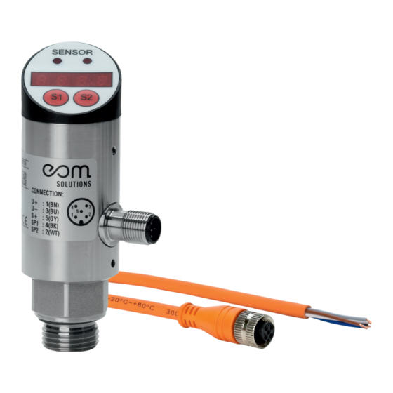
SCOPE OF DELIVERY Before installing the electronic pressure switch, please check that there has been no damage to the device. If any damage is apparent, please contact the eom-solutions GmbH. Illus. 2.1 Electronic Pressure Switch Documents Cable 1. Operating instructions 2. -
Page 7: Installation Of The Ept4000
INSTALLATION OF THE EPT4000 This chapter describes the installation of the EPT4000 electronic pressure switch. Installation and fastening WARNING Ensure that the system is not under pressure before installing or uninstalling. Connect the sensor device to the optional process interface Recommended tightening torque range: 25 to 35 Nm For critical applications (e.g. -
Page 8: Electrical Connections
Steps of the electrical installation: Switch off the power supply Wire the product according to the corresponding wiring method in the following figure. Illus. 3.3 brown 12~30VD white Switch 2 blue black Switch 1 grey mA/pulseP Illus. 3.4 Installation of the EPT4000... -
Page 9: Control Panel
CONTROL PANEL TASTENFUNKTIONEN → BUTTON S1 Menu item Increase numerical value → BUTTON S2 Menu item Decrease numerical value BUTTON S1 Press simultaneously → Enter menu or Exit menu BUTTON S2 BUTTON S2 → Reset value (5s) Check that there is no pressure before resetting Illus. -
Page 10: Operation
OPERATION Menu and settings To access the menu, press S1 + S2 simultaneously. The text "LOCK" then appears on the display. By pressing S1 or S2, it is possible to navigate up or down through the menu items. Menu items 0001 (switching value menu) and 0066 (top menu) are available for selection and parameter input. - Page 11 0066 Top menu DSAL The default value is 0 (overrange is deactivated). The value 1 represents the overrange. If the value range is exceeded (120 % of the max. value), the overrange indicator flashes BS-L By default, this value corresponds to the lower value of the measuring range.
- Page 12 Switch 1: Switching value Signal output when pressure reaches this value Switch 1: Release value Signal output is terminated when pressure reaches this va- Switch 1: Action delay ( resolu- tion: 0.1 s) Switch 1: Switchover Normally open / Normally close (NO/NC) Switch 2: Switching value Signal output when pressure reaches this value...
- Page 13 The default value is 0 (overrange is deactivated). The value 1 represents the overrange. If the value range is exceeded (120 % of the max. value), the overrange indicator flashes. By default, this value corresponds to the lower va- lue of the measuring range. An output signal of 4 mA corresponds to this value.
-
Page 14: Hysteresis Model
Hysteresis model The hysteresis function is mainly to keep the output of the switch stable when the pressure value fluctuates around the set value. In the process of pressure increase, when the pressure value is greater than AL1H, a signal is output. When the pressure value is less than AL1F, no signal is output. -
Page 15: Product Launch
PRODUCT LAUNCH Product launch The electronic pressure switch is used for intelligent regulation and control and has an integrated pressure measurement, a digital display and various output options. The output signal is processed by an amplifier with low temperature drift and converted into a digital signal for further processing in a high-precision A/D converter. -
Page 16: Error Code And Handling
ERROR CODE AND HANDLING EEPROM data check error. EREP Such an error occurs mainly during booting. A check or reset of the device is necessary to rectify the error. Switch 1 Output short-circuit -> Output deactivated Ero1 Troubleshooting: Eliminate short circuit and switch on again. Switch 2 Output short-circuit ->... -
Page 17: Contact
We`re here to help you! If you have any questions, please do not hesitate to contact us +43 3326 530 70 info@eom-solutions.at Hauptstraße 27, A - 7533 Ollersdorf im Burgenland Follow us on our social media channels. EOM SOLUTIONS WWW.EOM - SOLUTIONS.AT Contact... - Page 18 EPT4000 MANUAL EOM SOLUTIONS WWW.EOM - SOLUTIONS.AT EOM SOLUTIONS GMBH Energy Optimizing Monitoring Hauptstraße 27, A - 7533 Ollersdorf im Burgenland Telefon/Fax: +43 3326 530 70 (20) I Mail info@eom-solutions.at...
Need help?
Do you have a question about the EPT4000 and is the answer not in the manual?
Questions and answers