
Summary of Contents for Stortech SCS-12R/D2T
- Page 1 CAMERA MONITORING SYSTEM (CMS) MIRROR REPLACEMENT Installation and Programming Manual • SCS-12R/D2T • SCS-12R/D2TG • SCS-12R/D2TGA Version1 08/2023...
-
Page 2: Table Of Contents
Contents Basic Features Disclaimer Product Features Stortech Electronics does its best to ensure the integrity and accuracy of the contents in this Packing List document and cannot guarantee this. The outcome of using this document shall be entirely Installation the user’s own responsibility. Stortech Electronics reserves the right to change the contents Connection Diagram of this document without prior notice. -
Page 3: Basic Features
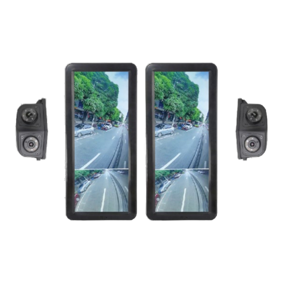
Overview Features Basic Features • Supports recording within 3-sec of powering up and video playback. • 12.3” 1920 x 3(RGB) x 720 HD Monitor resolution • Supports Micro SD Card, 512G max. • 2 – 1 Monitor and recording function. With ACC input, support ACC time lapse recording •... -
Page 4: Installation
Installation Connection Diagram 12.3” Digital colour LCD screen GPS antenna Class II camera (optional) SD Card Slot Class IV camera Single red wire to power wire of DC: 10-32V. Single orange wire to ACC Single black wire to GND. Single white wire to Camera_L. Single blue wire to Camera_R. - Page 5 Operation Instruction CONNECTIONS Connections • Single Red Wire: To +ve Power supply for DC: 10 ~32V. • Single Orange Wire: To ACC. Single Black Wire: To GND •...
-
Page 6: Product Features
Monitor Installation • Distance between the monitor and the ORP • 12.3” HD Review Electronic Mirro System, according to regulation R46. • Class II fields of vision • Class IV fields of vision • Lock the monitor and the bracket with supplied screws (4 * M4*10) -
Page 7: Camera Positioning
Operation Instruction Monitor Camera • Fix the back plate to the right place in a vehicle with four screws as The installation position of the horizontal • shown. distance and height is shown below. Back Plate • Hang the monitor and bracket upside down to the back plate as, adjust the angle of the monitor, then fix with the corresponding screws (2 pcs * M3). -
Page 8: Ir Remote Control
IR REMOTE CONTROL VOL: Move menu cursor right & increase volume VOL: Move menu cursor left & decrease volume Move menu cursor up. DOWN: Move menu cursor down. REST: Reset the system AV: Start / Stop recording SEL: Select the menu the cursor has highlighted. MENU: Exit to the main menu or return to the previous menu. -
Page 9: File List
File List Type: Video file type selection, including Normal and Event Hour: Time period containing the video files Search: Displays video files list based on filter criteria. Select: Select recording file. All: Select / unselect all files. ... -
Page 10: Settings
Setting Function Description • Display: Screen parameter settings. • Record: Video recording settings. System: System configuration. • • Disk: Memory card management. Calibration: Calibrating grid lines Green, Yellow, Red • Reset: Restore factory settings. • Setting Function Description: Select the different options using the up and down keys, while the values are changed using the left and right keys. -
Page 11: System
System • To enter the Dimmer setting interface, select Dimmer and press “SEL” button on the IR remote controller. • To enter the Date & Time setting interface, select Date & Time and press “SEL” button on the IR remote controller. Dimmer When Auto is On, the monitor turns on the automatic backlight function and switches the monitor to brighten/darken depending on... -
Page 12: Disk
Disk Total: Total disk capacity. Free: Current remaining capacity Format: To format the SD Card, press the “SEL” button on the IR remote controller to format the storage media. Upgrade When the SD card contains the upgrade file, the version number will be displayed. -
Page 13: Reset
Reset Reset: Restore factory settings button, click OK to enter the reset mode. All parameters will be restored to default values. The system will reboot after completion. Click cancel to exit. e-mirror with AI option only Button Panel Instructions: • ± Moves the cursor •... - Page 14 BSD Configuration mode: • Press the UP / DOWN / VOL / VOL button of the IR remote control to adjust the position of the BSD line. • Press the P/N button of the IR remote control to switch the BSD line focus. •...
- Page 15 Specifications Back Light Compensation Auto Gamma 0.45 MONITOR Auto Auto White Balance LCD Size 12.3” >100dB Resolution 1,920(H) X 720(V) 3(RGB) 1/30(1/25) ~ 1/50,000 Seconds Electronic Shutter Contrast 1,000:1 LENS Maximum Brightness 1,000cd/m Focal Length 2.3mm (Lower Camera) / 6.0mm (Upper Response Time 120ms Camera)
- Page 16 Whilst every effort has been made to ensure the accuracy of the information provided, no liability can be undertaken for any errors or omissions. All dimensions stated in this document are approximate. Stortech Electronics Ltd reserves the right to alter the specifications and introduce changes...
Need help?
Do you have a question about the SCS-12R/D2T and is the answer not in the manual?
Questions and answers