Table of Contents
Advertisement
Quick Links
10/23
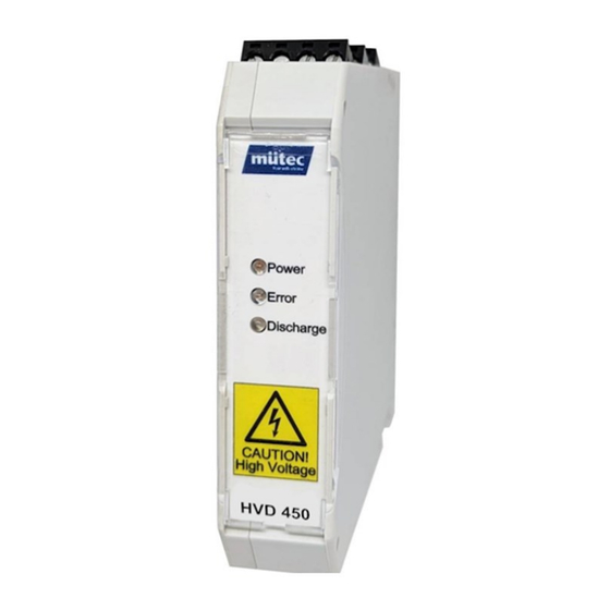
Application
As industries shift to higher voltages of up to
1500V in DC links, efficient energy storage and
discharge systems are crucial. Traditionally,
mechanical contactors were used but faced
wear and tear when switched under load. The
HVD 450 eliminates this issue by seamlessly
switching discharge circuits without wear down,
ensuring long-lasting performance. It integrates
precise current and voltage monitoring for real-
time surveillance of the discharge process.
Control is simple and efficient with a standard
5-24V signal from a PLC. The device provides
comprehensive feedback on the discharge
process, including potential errors or hazards.
Experience the future of discharge technology
with the HVD 450.
Mütec Instruments – Your safe choice
Bei den Kämpen 26
D-21220 Seevetal-Ramelsloh
731
Safe and wear-free
discharging of High Voltage
Features
-
SiC-based solid state contactor
-
Wear-free switching of high voltage
DC links
-
Fast discharge times due to high
current (8A per device, multiple
devices in parallel are possible to
multiply the current)
-
Integrated current and voltage
monitoring
-
Robust and intelligent replacement
for discharging contactors
-
Status outputs and signalling of
potential hazards
Tel.: +49 4185/8083-0
Fax: +49 4185/8083-80
HVD 450
DC links
Mail:
muetec@muetec.de
Web:
www.muetec.de
1
Advertisement
Table of Contents

Summary of Contents for Mutec HVD 450
- Page 1 (8A per device, multiple wear and tear when switched under load. The devices in parallel are possible to HVD 450 eliminates this issue by seamlessly multiply the current) switching discharge circuits without wear down, Integrated current and voltage monitoring ensuring long-lasting performance.
- Page 2 10/23 Manual HVD 450 Doc-Nr.: Revision: 2.5 Issue date: 10/2023 Manufacturer: Mütec Instruments GmbH Bei den Kämpen 26 21220 Seevetal Deutschland Tel.: +49 (0) 4185 8083-0 Fax: +49 (0) 4185 808380 E-Mail: info@muetec.de Internet: www.muetec.de Licence-, trademark and copyright notes Copyright ©...
-
Page 3: Table Of Contents
Example calculation for the discharge parameters ..............16 Setting the time constant ......................17 Increase Discharge Currents by Parallelization ............17 Functional description of the HVD 450 ..............18 Measurement ..........................18 Measurement accuracy ....................... 18 Discarge Process ......................... 18 Possible Error Causes ......................... -
Page 4: Safety Instructions And Installation
10/23 Safety instructions and installation HAZARD: High Voltage / Danger to Life The device is designed for secondary voltages of up to 2000 V. and may only be used in safe operating environments. The specified safety conditions and safety guidelines (including national safety guidelines, accident prevention regulations) must be observed for installation and operation. -
Page 5: Safety Instruction Classifiction
10/23 Safety Instruction Classifiction This manual contains instructions that you have to observe for your personal safety as well as to avoid material damage. These instructions are highlighted using a triangular warning sign and shown as follows, depending on the degree of risk. HAZARD means that death or severe physical injury will occur if the appropriate precautionary measures are not taken. - Page 6 10/23 CAUTION without a triangular warning sign means that material damage may occur if the appropriate precautionary measures are not taken. ATTENTION means that an undesired result or state may ensue if the corresponding instruction is not followed. NOTE denotes important information about the product, handling of the product or the respective part of the documentation, is aimed at drawing special attention to the latter and should be complied with.
-
Page 7: General Instructions
All modifications to the device fall within the responsibility of the user unless expressly specified otherwise in the operating manual. VALIDITY The data sheet is only valid for the HVD 450 described and the hardware / firmware version specified in the technical data Mütec Instruments – Your safe choice Bei den Kämpen 26... - Page 8 10/23 QUALIFIED PERSONNEL Qualified personnel are persons who, due to their training, experience and instruction as well as their knowledge of relevant standards, regulations, accident prevention regulations and operating conditions, have been authorized by the person responsible for the safety of the system to carry out the necessary planning and activities and thereby recognize and recognize possible dangers can avoid.
- Page 9 Take measures to prevent polarity reversal or manipulation of the connections. DEVICE IN OPERATION During operation, the input section of the HVD 450 is under dangerously high voltage. Do not remove any protective cover (blind cap between the terminal blocks) or cables on the terminals during operation.
- Page 10 10/23 ELECTROSTATIC DISCHARGE Potentially electrostatic components may be destroyed by voltage that is far below the limits of human perception. Such voltage occurs even when you touch a component or electrical connections of a component and are not electrostatically discharged. The damage that occurs to a component because of overvoltage usually cannot be detected immediately and does not become noticeable until after a longer operating period.
-
Page 11: Technical Data
10/23 Technical Data Load Output T-21/22(+) and T-25/26(-) Voltage U ≤ 1500 V Max. DC link voltage Current I ≤ 8 A Max. discharge current Current I ≥ 9.6 A Limit value current alarm Residual voltage U: < 10 V Discharge time constant ��: 100 ms …... -
Page 12: General Data
10/23 General Data Environmental Conditions Operation: -10 °C … +60 °C Storage/Transport: -20 °C … +80 °C Perm. Rel. Humidity (during operation): 10 % … 95 % r. H. no. Cond. Max. operating altitude:: ≤ 2000m above mean sea level Galvanic Isolation 3 port isolation: Input / output / supply... -
Page 13: Installation
10/23 4.10 Installation TBUS-Connection TBUS-Connector with DIN-rail Mounting and dismounting of a DIN-rail housing Figure 1 - DIN-rail housing and mounting Important note: The device may only be attached to or removed from the TBUS-Connection when power is switched off! Attach the housing to a 35 mm DIN-rail according to EN 60715. -
Page 14: Housing Dimensions
10/23 4.11 Housing Dimensions Figure 2: Housing Dimensions 4.12 Block diagram Figure 3: Block diagram and galvanic isolations Mütec Instruments – Your safe choice Bei den Kämpen 26 Tel.: +49 4185/8083-0 Mail: muetec@muetec.de D-21220 Seevetal-Ramelsloh Fax: +49 4185/8083-80 Web: www.muetec.de... -
Page 15: Nameplate
10/23 4.13 Nameplate Figure 4: Nameplate Connection to the DC Link Figure 5: connection of HVD 450 to DC Links Curves and functions of the discharge process Mütec Instruments – Your safe choice Bei den Kämpen 26 Tel.: +49 4185/8083-0 Mail: muetec@muetec.de... -
Page 16: Example Calculation For The Discharge Parameters
10/23 Example calculation for the discharge parameters = current limiting resistor = Capacitor voltage (e.g. 1600V) = max. current (≤ 8 A) = DC Link capacity (e.g. 1000 µF) External resistor R = 1600 V / 8 A = 200 Ω Time constant ��... -
Page 17: Setting The Time Constant
Setting the time constant For monitoring the discharge process of the capacitance from the DC link, the time constant "T" must be set in the HVD 450. This time constant "T" must always be greater than the time constant R x C. -
Page 18: Functional Description Of The Hvd 450
10/23 Functional description of the HVD 450 Measurement A measurement interval of 100μs is used to measure the discharge voltage. The measurements are averaged within a time window of 1ms. This means that every millisecond a new measured value is available. - Page 19 10/23 Figure 7: DC Link voltage function The maximum time constant (�� = R x C) for discharge shall be 100ms. Calculation of the discharge time: The time required to achieve a voltage drop of 20% at 100ms is calculated. The calculation also takes into account the measurement error.
-
Page 20: Possible Error Causes
10/23 Possible Error Causes Figure 8: Failed discharge due to exceeding the assumed time constant Mütec Instruments – Your safe choice Bei den Kämpen 26 Tel.: +49 4185/8083-0 Mail: muetec@muetec.de D-21220 Seevetal-Ramelsloh Fax: +49 4185/8083-80 Web: www.muetec.de... -
Page 21: State Overview
10/23 Figure 9: Failed discharge due to increasing voltage (e.g. re-activiation of DC link supply) State Overview Table 1: Status overview Power Error Discharge Status Note Switched off No supply connected Ready Device ready to discharge Discharging Discharge in progress Cooldown Protective measure... -
Page 22: State Diagram
10/23 State Diagram To clarify the behaviour of the device and the resulting states defined in chapter 7.5, the following state diagram shows the operation modes of the devices. After the boot procedure, the device switches to the ready state (applying the Start signal before powering up the device leads to an error). - Page 23 10/23 HAZARD To reset the device from the error state, a power cycle is required. Please do not reset the device without checking the potential reasons for the error to occur. After discharging, the device automatically enters a cooldown state. If the Start signal is set to low, the devices is ready for operation again.
- Page 24 10/23 If you have any questions or concerns, please do not hesitate to contact us! Mütec Instruments GmbH Bei den Kämpen 26 D-21220 Seevetal-Ramelsloh Germany Tel.: + 49 (0)4185-8083-0 Fax: + 49 (0)4185-8083-80 Mail: muetec@muetec.de Web: www.muetec-instruments.de Follow us on Linkedin! www.linkedin.com/company/muetec Mütec Instruments –...
Need help?
Do you have a question about the HVD 450 and is the answer not in the manual?
Questions and answers