Advertisement
Quick Links
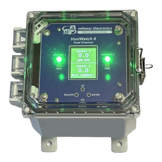
VOXI
MP883 Dual Channel
Quick Start Guide
mPower Electronics Inc.
2910 Scott Blvd. Santa Clara, CA 95054
www.mpowerinc.com
info@mpowerinc.com
PN: M028-4010-0
User Interface
The MP883 is a remote controller, display and alarm
for one or two VOXI transmitters. The user interface has
an LCD graphic display, LED indications and 4 push-
buttons for programming.
Controller
00
The VOXI Controller full User's Guide must be
carefully read by all individuals who have the
responsibility of using, maintaining, or servicing this
product. The product will perform as designed only if it is
used, maintained, and serviced in accordance with the
manufacturer's instructions.
• The MP883 Controller is NOT certified for use in hazardous
gas locations. VOXI gas transmitters in hazardous locations
may be connected to it with appropriate cabling.
• Never operate the Controller when the cover is removed.
• Remove the Controller cover only in a non-hazardous area.
• Use only mPower's sensors and accessories. Substitution of
components will impair intrinsic safety and void warranty.
Using the four mounting feet and attach to any solid
surface in a non-hazardous-gas location. The VOXI
transmitters may be mounted in hazardous locations with
appropriate cabling connecting to the MP883 Controller
outside the hazardous area.
v1.0
Relay Board 4-20 mA Channels and RS-485 Modbus
2
Read Before Operating
Warnings
Mounting
Wiring Connections
Relay Board Alarms &
1
Relay Output/Load
3
Advertisement

Subscribe to Our Youtube Channel
Summary of Contents for mPower Electronics VOXI MP883
- Page 1 The VOXI transmitters may be mounted in hazardous locations with appropriate cabling connecting to the MP883 Controller outside the hazardous area. mPower Electronics Inc. 2910 Scott Blvd. Santa Clara, CA 95054 www.mpowerinc.com info@mpowerinc.com PN: M028-4010-0 v1.0...
- Page 2 SD Card Start Up Display A user-provided 32GB SD card can optionally be used to log events such as power on/off, calibration, alarms, and faults. Insert the card in the slot on the back side of the main circuit board. If no SD card is present, Channel 2 LED will show solid red during the 60-sec power on warmup period.
- Page 3 Programming (continued) Programming (continued) • Sub-Menus Channel 1 or Channel 2 The sub-menus are listed below Calibration Function Channel 1 or Channel 2 Reading Current reading Configure Function Gain Channel gain adjustment Name Channel name Offset Channel offset adjustment Gas name Device Measure Gas unit...
Need help?
Do you have a question about the VOXI MP883 and is the answer not in the manual?
Questions and answers