
Summary of Contents for Aurora Scientific 604A-STIM
- Page 1 Signal Interface 604A/604D/604E/-STIM/-PHOTON Publish Date: 5/9/2022 Manual Version 2 www.AuroraScientific.com © Aurora Scientific, 2022 VER. 2.00 page 1...
- Page 2 Signal Interface Instruction Manual Model: 604A/604D/604E/-STIM/-PHOTON Copyright © 2022 Aurora Scientific. Aurora Scientific 25 Industry Street Aurora, ON, Canada L4G1X6 Tel: 1-905-727-5161 Toll Free (N. America): 1-877-878-4784 Fax: 1-905-713-6882 Email: techsupport@aurorascientific.com Web Site: www.AuroraScientific.com © Aurora Scientific, 2022 VER. 2.00...
- Page 3 Signal Interface Instruction Manual Model: 604A/604D/604E/-STIM/-PHOTON Revision History Date Version Document Changes Number 17-Nov-2020 1.0 Initial Draft 9-May-2022 2.0 Added -STIM, -PHOTON and 604D © Aurora Scientific, 2022 VER. 2.00 page 3...
-
Page 4: Table Of Contents
Performance Guarantee, Technical Support, Warranty and Repair Information ......30 ..Performance Guarantee ..........................30 ..Technical Support ............................30 ..Technical Support Contact Information and Return Shipping Addresses............30 ..Warranty ................................ 31 © Aurora Scientific, 2022 VER. 2.00 page 4... - Page 5 Signal Interface Instruction Manual Model: 604A/604D/604E/-STIM/-PHOTON ..Returning Products to Aurora Scientific for Repair ..................32 Specifications ..........................33 © Aurora Scientific, 2022 VER. 2.00 page 5...
-
Page 6: Introduction
There are six (6) (604A) or four (4) (604E) digital input/output (Digital I/O) connectors labeled I/O 1 through I/O 6 for the 604A and I/O 1 through I/O 4 for the 604E. Aurora Scientific Inc. software (either DMC LabBook or 600A) configures the I/O ports to be either inputs or outputs depending on what is required for the experiment. - Page 7 On the back of the 604A/E Signal Interface are one (604A) or two (604E) data connectors that accept a shielded 2-m long VHDCI data cable that plugs into a National Instruments PC-based A/D card in a PC. © Aurora Scientific, 2022 VER. 2.00...
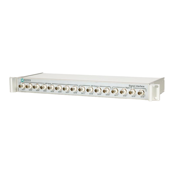
- Page 8 604E Signal Interface and provides the user with a computer-controlled switch that is integrated with Aurora Scientific data acquisition and control software. When included with a 604A/E Signal Interface the overall package consists of a 1U (1.75”) high, 19” wide, rack-mount case with BNC connectors on the front and back panels, data connector(s) on the back along with a 12VDC power input connector.
- Page 9 Signal Interface. The Counter input lines required to measure the photon count signals are connected internally to the required ports on the National Instruments A/D card. Figure 4 604A-PHOTON Signal Interface Back Panel © Aurora Scientific, 2022 VER. 2.00 page 9...
- Page 10 Thus, it accepts up to 16 analog input signals, 4 D/A outputs and 12 Digital I/O lines. Two data cables are connected inside the case and are available to plug into two National Instruments data acquisition cards located in a PC. © Aurora Scientific, 2022 VER. 2.00 page 10...
-
Page 11: Quick Start Guide
12VDC power supply, and a power cord for the power supply (compatible with the power sockets in your region) Table 2 Items included with a 604A/E-STIM Signal Interface with Stimulator Switch © Aurora Scientific, 2022 VER. 2.00 page 11... -
Page 12: First Time Operation Of The 604A/E Signal Interface
4. Connect the front-panel BNC connectors to your instruments using the BNC-BNC cables provided. The tables in section 2.2 below show the connections used for all Aurora Scientific instruments. 5. Once you have connected your instruments you can start the software and check that your signals are being received correctly and that the software is controlling your instruments. -
Page 13: First Time Operation Of The -Stim Stimulator Switch
3. Connect the front-panel BNC connectors to your instruments using the BNC-BNC cables provided. The tables in section 2.2 show the connections used for all Aurora Scientific instruments. 4. Once you have connected your instruments you can start the software and check that your signals are being received correctly and that the software is controlling your instruments. -
Page 14: Connections To Other Instruments
A/D 3 Length Out A/D 4 Force Out A/D 5 – A/D 8 = 50Ω Terminator D/A 1 Length In D/A 2 Force In D/A 3 Length In D/A 4 Force In © Aurora Scientific, 2022 VER. 2.00 page 14... - Page 15 Connecting the 604E to a High-Speed Length Controller (315C/D or 322C/D) and 400A/B/C Force Transducer 604EA Signal Interface 315C/D or 322C/D Lever 400A/B/C Force Transducer A/D 1 Length Out A/D 2 Force Out A/D 3 – A/D 8 50Ω Terminator D/A 1 Length In © Aurora Scientific, 2022 VER. 2.00 page 15...
- Page 16 Connecting the 604A to a 701C Stimulator 604A Signal Interface 701C Stimulator I/O 3 Pulse Trigger Connecting the 604E to a 701C Stimulator 604E Signal Interface 701C Stimulator I/O 3 Pulse Trigger © Aurora Scientific, 2022 VER. 2.00 page 16...
-
Page 17: Dmc Labbook Connections
A/D 4 Aux 2 A/D 5 Aux 3 A/D 6 Aux 4 A/D 7 Aux 5 A/D 8 Aux 6 D/A 1 Length Out D/A 2 Force Out I/O 1 Trg In 1 © Aurora Scientific, 2022 VER. 2.00 page 17... - Page 18 Aux 2 Aux 2 Aux 2 Aux 2 Aux 3 Aux 3 Aux 3 Aux 3 Aux 4 Aux 4 Aux 4 Aux 4 Aux 5 Aux 5 Aux 5 Aux 5 © Aurora Scientific, 2022 VER. 2.00 page 18...
-
Page 19: 600A Connections
Length Out D/A 2 Force Out I/O 1 Trg In 1 I/O 2 Trg In 2 I/O 3 Stimulator I/O 4 Inhibit I/O 5 Trg Out 1 I/O 6 Trg Out 2 © Aurora Scientific, 2022 VER. 2.00 page 19... - Page 20 A/D 7 Length In 4 A/D 8 Force In 4 D/A 1 Length Out 1 D/A 2 Length Out 2 D/A 3 Length Out 3 D/A 4 Length Out 4 I/O 1 Stimulator © Aurora Scientific, 2022 VER. 2.00 page 20...
- Page 21 Signal Interface Instruction Manual Model: 604A/604D/604E/-STIM/-PHOTON I/O 2 Inhibit I/O 3 Trg Out 1 I/O 4 Trg Out 2 © Aurora Scientific, 2022 VER. 2.00 page 21...
-
Page 22: Connections
Signal Interface Instruction Manual Model: 604A/604D/604E/-STIM/-PHOTON 3 Connections 3.1 604A/D Signal Connections (604D has 2 complete versions of this connection table) Table 6 604A/D (including -STIM and -PHOTON) Connector 0 Connections © Aurora Scientific, 2022 VER. 2.00 page 22... -
Page 23: 604E Signal Connections
Signal Interface Instruction Manual Model: 604A/604D/604E/-STIM/-PHOTON 3.2 604E Signal Connections Table 7 604E (including -STIM and -PHOTON) Connector 0 Connections © Aurora Scientific, 2022 VER. 2.00 page 23... - Page 24 AI SENSE 2 NC AI GND AI 27 AI 19 AI GND AI 26 AI 18 AI GND AI 25 AI 17 AI GND AI 24 AI 16 Table 8 604E Connector 1 Connections © Aurora Scientific, 2022 VER. 2.00 page 24...
-
Page 25: Calibration And Troubleshooting
Interface the calibration is and end-to-end calibration that is done using either DMC LabBook or 600A. 4.2 Troubleshooting The table below summarizes potential problems and their solutions. If these recommendations do not resolve the problem, please contact Aurora Scientific Inc. for further assistance. Problem Recommended Action... -
Page 26: -Stim And -Photon Setup And Operation
604A/E Signal Interface. National Instruments digital I/O lines P0.0 and P0.7 are used to control the stimulator switch. If using Aurora Scientific Inc. software, then these ports are automatically connected, and the stimulator switch will work as soon as you start the software. If you are using your own software, then configure the two ports as shown below to control which output is active as show in the table below. -
Page 27: Photon Setup And Operation
2) Observe the -PHOTON PCB (see Figure 12) and you will see two potentiometers labelled R2 for Counter 1 and R7 for Counter 2. Turning the potentiometer clockwise will increase the output © Aurora Scientific, 2022 VER. 2.00 page 27... - Page 28 (one that had the black wire attached to it). 4) Observe the output pulse width on the oscilloscope. 5) Once you have completed setting the potentiometers replace the top panel and screws. Figure 12 -PHOTON PCB Installed in 604A/E © Aurora Scientific, 2022 VER. 2.00 page 28...
-
Page 29: Troubleshooting The -Photon
If you don’t see any counts with a function generator then there may be issues with the -PHOTON PCB or with the NI card. Table 13 -PHOTON Troubleshooting Chart © Aurora Scientific, 2022 VER. 2.00 page 29... -
Page 30: Performance Guarantee, Technical Support, Warranty And Repair Information
Our performance guarantee states: if for any reason a new product does not meet your research needs then you can return it to Aurora Scientific for exchange or a full refund. The performance guarantee only applies to new products and must be exercised within 60 days of receipt of the instrument. -
Page 31: Warranty
Products manufactured by Aurora Scientific Inc. are guaranteed to the original purchaser for a period of three (3) years. Under this warranty, the liability of Aurora Scientific is limited to servicing, adjusting and replacing any defective parts that are of Aurora Scientific manufacture. Aurora Scientific is not liable to the customer for consequential or other damages, labour losses or expenses in connection with or by reason of the use or inability to use the products manufactured by Aurora Scientific. - Page 32 SHALL BE VALID UNLESS MADE IN WRITING AND SIGNED BY AN EXECUTIVE OFFICER OF AURORA SCIENTIFIC INC. 6.5 Returning Products to Aurora Scientific for Repair There are a few simple steps that must be completed before returning your product to Aurora Scientific. Obtain a Return Material Authorization number (RMA#). Go to our website or contact our technical support department to obtain a RMA #.
- Page 33 Internal connections to I/O P0.0 and P0.7 General Specifications Operating Temperature [°C] 0 - 40 Power Required 100-240VAC Power Consumption [W] Weight [kg] (604A/E Interface) Dimensions [cm] x 13.5D x 4.5H (19” rack mount) (1U) (604A/E Interface) © Aurora Scientific, 2022 VER. 2.00 page 33...
- Page 34 0 - 40 Power Required Internal +5VDC from NI card Power Consumption [W] Weight [kg] (604A/E Interface) Dimensions [cm] x 13.5D x 4.5H (19” rack mount) (1U) (604A/E Interface) Output Pulse Width = 550nsec © Aurora Scientific, 2022 VER. 2.00 page 34...
Need help?
Do you have a question about the 604A-STIM and is the answer not in the manual?
Questions and answers