Advertisement
Advertisement
Table of Contents

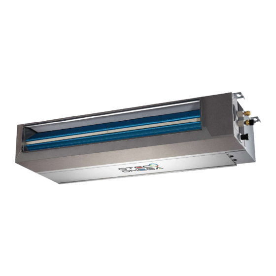
Summary of Contents for Omega IEMP-D Series
-
Page 2: Table Of Contents
CONTENTS PAGE WARNING PRECAUTIONS..................1 If the supply cord is damaged, it must be replaced by the OVERVIEW....................2 manufacturer or its service agent or a similarly qualified person INSTALLATION..................3 in order to avoid a hazard. An all-pole disconnection switch having a contact separation of ELECTRICAL CONNECTION..............10 at least 3mm in all poles should be connected in fixed wiring. -
Page 3: Overview
An insufficient power supply capacity or inappropriate installation 2. OVERVIEW may cause fire. Use the specified cables for wiring connect the terminals securely fix. To prevent external forces applied to the 2.1 Accessories terminals from affecting the terminals. Be sure to provide grounding. SHAPE QUANTITY NAME... -
Page 4: Installation
3. INSTALLATION CAUTION Choose the correct move-in path. 3.1 Choosing an Installation Site Carry the device in its original package. Electrical insulation measures can be taken in accordance Enough space for installation and maintenance. with relevant technical specifications of electrical equipment if The ceiling is level, and the structure is strong enough to support the air conditioner is to be installed onto the metal part of a the weight of IDU;... - Page 5 External dimensions and size of air outlet duct To match the existing structure, set the screw pitch according to the product dimensions shown below. Wooden structure Place the square bar by crossing the beams and set the lifting bolts. Square bar material Beam Ceiling Lifting bolt...
- Page 6 CAUTION All bolts should be made from high quality carbon steel (with Air inlet grille Air inlet direction galvanized surfaces or other rust preventive treatment) or stainless steel. Fig 3-1 How the ceiling is treated will differ with the type of building. For specific measures, please consult the building and renovation engineers.
- Page 7 >600 Fixed with a bolt Fig 3-5 Drain pan assembly Figure d: Shift the drain pan downwards until the drain pan is >2000 >500 >3000 >3000 >300 removed from the unit body 3.3 ODU Installation Fig 3-6 WARMING The ODU can be installed only by qualified professionals. >300 Improper installation by the user will lead to accidents such >600...
- Page 8 Use the attached water discharge hose to connect to the drainage outlet and PVC piping of the indoor unit. Use the provided ring clamps to clasp tightly (see Fig 3-8). Rope Use hard PVC adhesives for connecting to other water piping. Check that the connections are tight with no leakage.
- Page 9 1. Before the test, make sure that the water discharge pipeline is Measure the required length of the connecting pipe. Make the smooth, and check that each connection is sealed properly. connecting pipe using the following method (see the column Pipe Connection for details).
- Page 10 1. Bend the pipe or drill a hole in the wall as needed. The Use a vacuum pump to discharge the air. cross-sectional area of the pipe bending deformation must not Loosen and remove the service port nut of check valve A and exceed 1/3 of the original pipe section.
-
Page 11: Electrical Connection
After installation, the check valve must be fully opened before the test run. Each unit has two valves of different sizes located on the Manually switch fan speed to set to high static pressure mode ODU side as the low pressure valve and high pressure valve. The (super-high for high static pressure mode) operation of opening and closing the check valve is shown in the following figure. - Page 12 Model Power Supply Maximum operating Recommended Power cord Ground line Communication current (A) circuit breaker (A) (AWG) (AWG) wire (AWG) 220-240V 50Hz 2×10 3×18 220-240V 50Hz 2×18 3×18 220-240V 50Hz 2×10 3×18 220-240V 50Hz 2×18 3×18 220-240V 50Hz 2×10 3×18 220-240V 50Hz 2×18 3×18...
-
Page 13: Trial Run
3. Install the remote controller mounting rack according to the user's NOTE requirements. The location of the mounting rack must be such that the remote control signal can be successfully transmitted to the indoor unit. Remove the electric box cover of the outdoor unit (two screws). 4. - Page 14 1. First create a gap of 50 mm x 135 mm in the ceiling where the unit will be mounted. Ceiling 135mm 2. Turn up the spring on the control box. Spring Control box 3. First properly connect the connecting lines to the indoor unit. Position the control box directly at the ceiling opening, and exert force to press it into the ceiling, until you hear a "click"...


Need help?
Do you have a question about the IEMP-D Series and is the answer not in the manual?
Questions and answers