Table of Contents
Advertisement
Quick Links
Advertisement
Table of Contents

Related Manuals for SatRover MK1

Summary of Contents for SatRover MK1
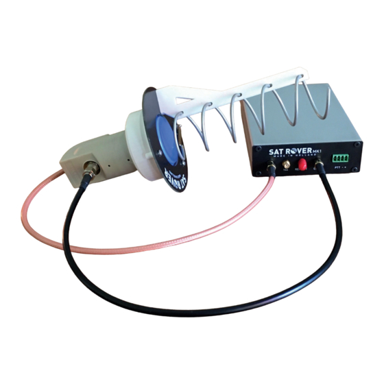
- Page 1 QO100 TRANSVERTER User Manual Type: SatRover MK1 - Version: 4 november 2023...
-
Page 2: Table Of Contents
SatRover MK1 - User Manual QO100 Transverter Table of contents Introduction Dimensions and specifications Dimensions Specifications Block diagram Assembly Unpack and identify parts. Assembly steps Installation and interface Source supply Radio connection Antenna set-up LNB / helix connection Getting started Antenna aiming Making QSO’s... -
Page 3: Introduction
• Coaxial cable between 144 MHz transceiver and SatRover. The SatRover is developed with simplicity in mind. The “Rover” in the name means it is intended to use on portable or “Rover” operation. Together with a portable 144MHz transceiver it is small enough to put in your backpack or with your camping gear. -
Page 4: Dimensions And Specifications
SatRover MK1 - User Manual QO100 Transverter 2 Dimensions and Specifications 2.1 Dimensions Transverter enclosure: Length 165 mm Width 105 mm Hight 40 mm LNB/Helix: Length 200 mm Diameter 100 mm Mount diameter 40 mm (standard LNB mount) 2.2 Specifications TX frequency range 2400.0 –... - Page 5 SatRover MK1 - User Manual QO100 Transverter IF input-output / impedance SMA female 50 Ohm LNB input / impedance SMA female 50 Ohm 25.23 MHz Ref output / impedance SMA female 50 Ohm RF output / impedance SMA female 50 Ohm...
-
Page 6: Block Diagram
SatRover MK1 - User Manual QO100 Transverter 3 Block Diagram • LNB: IF= 649 MHz / REF = 25.23 MHz • RF UIT: 2400 MHz • IF: 144.5 – 145 MHz • REF UIT: 25.23 MHz... -
Page 7: Assembly
SatRover MK1 - User Manual QO100 Transverter 4 Assembly This transverter intended to be used by radio amateurs. Due to European regulation the radio amateur must do the final assembly their self. This chapter guides you through this assembly process. To simplify this process there are only a few parts to assemble. -
Page 8: Installation And Interface
(Yeasu FT290 is interfaced this way) 2 The most left pin of the 4 pin multipole connector needs a pull down to make the SatRover go to transmit. (Icom IC705 can be interfaced this way) -
Page 9: Antenna Set-Up
• Do not use longer cables! The coax losses on 2,4 GHz are very high, this may affect your signal strength on TX. • The SatRover is not waterproof. If you want to use it in wet weather, you make yourself some kind of waterproof enclosure. -
Page 10: Getting Started
6 Getting started Before using your SatRover you must aim the antenna to the satellite. Be sure there is a window to the satellite from the location where you want to set up the antenna. There are many apps or websites to find the proper azimuth and elevation heading. -
Page 11: Adjustments
7 Adjustments It is possible to make some adjustments to the SatRover. The power output can be adjusted to match the drive power on 144MHz, both TX frequency and RX frequency can be set individually. To make these settings you must take off the top half of the enclosure. Before any adjustments are made warm up the transverter for at least 5 minutes to settle the OCXO 10MHz frequency. - Page 12 Holsink Holding BV Hilvertsweg 285 1214 JG Hilversum The Netherlands e-mail holsink@hetnet.nl website www.hybridpretender.nl...
Need help?
Do you have a question about the MK1 and is the answer not in the manual?
Questions and answers