Table of Contents
Advertisement
Quick Links
Advertisement
Table of Contents

Related Manuals for UNITRA WSH-805

Summary of Contents for UNITRA WSH-805
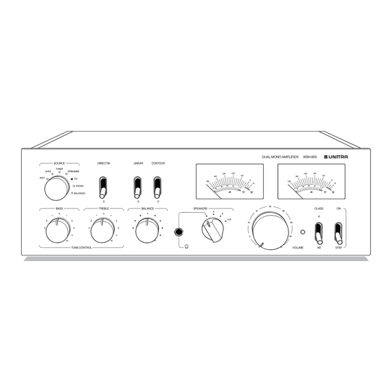
- Page 1 WSH-805 DUAL MONO AMPLIFIER User Manual...
-
Page 2: Table Of Contents
Contents Manufacturer Manufacturer Unitra sp. z o.o. Przejazdowa 2b, About this document 02-496 Warsaw, Poland Symbols used in this manual ......4 website: www.unitra.com... -
Page 3: About This Document
About this document Thank you for purchasing this Unitra product. To ensure proper operation, read this manual carefully and operate the device in accordance with the instructions contained in it. Please keep this manual for future reference after reading it. -
Page 4: Acronyms, Abbreviations, And Technical Terms
Description Content of the package Make sure that the following elements are included in the package: • Device (WSH-805 Dual Mono Amplifier) • Power cord • Other cables (if specified in your order) • Remote control (battery type CR2032 included) •... -
Page 5: Front Panel Overview
Front panel overview SOURCE selector switch and indicators The indicator light for the selected input source goes on. AUX1/AUX2 Selects the devices connected to AUX1 or AUX2 jacks as the input source. TUNER Selects the tuner connected to the TUNER jacks as the input source. - Page 6 DIRECT IN switch Switch up Selects the external preamplifier connected to the DIRECT IN jacks as the input source. Switch down Deselects the DIRECT IN; the input source is as selected by the SOURCE selector switch. NOTE When DIRECT IN is set to ON, the SOURCE indicators are off. The input signal bypasses the internal preamplifier block of the Device.
- Page 7 VU meters To indicate the audio output level of the left and right channel in dB. "0" on the upper scale is set to reflect the maximum level of test signal (sinusoidal) without distortion when connected to a speaker set with impedance of 8 Ω. The lower scale is dedicated to the class A output.
- Page 8 SPEAKERS selector switch Audio signal is output to the headphones connected to the headphones jack. Audio signal is output to the SPEAKERS A terminals. Audio signal is output to the SPEAKERS B terminals. Audio signal is output to the SPEAKERS A and B terminals. Select this position when you use a bi-wired connection.
-
Page 9: Rear Panel Overview
Rear panel overview AUX1 jacks To connect any type of devices as the input source. AUX2 jacks To connect any type of devices as the input source. TUNER jacks To connect tuner devices as the input source. STREAMER jacks To connect streamer players as the input source. CD jacks To connect CD players as the input source. - Page 10 You can use the DIMM key on the remote control to adjust the brightness of other Unitra devices. To synchronize the brightness of all the Unitra devices, press and hold the DIMM key on the remote control. The brightness of all the devices is automatically set to 0.
- Page 11 GND LIFT switch NORM The analog ground of the Device is connected to the case ground and electrical grid. LIFT The analog ground of the Device is disconnected from the case ground and electrical grid. Use this function in case of problems with humming sounds. NOTICE It is recommended to use the LIFT function when devices connected to the Device have a PE wire and do not have isolated analog connections...
-
Page 12: Remote Control Overview
11. NOTE You can use the DIMM key on the remote control to adjust the brightness of other Unitra devices. To synchronize the brightness of all the Unitra devices, press and hold the DIMM key on the remote control. The brightness of all the devices is automatically set to 0. - Page 13 SOURCE keys To select the input source. Each push selects the previous or the next input source in line. The SOURCE indicator light for the selected input source goes on. p. 6. VOLUME − / + keys To adjust the volume level of the Device. NOTE If you select the device connected to the DIRECT IN jack as the input source you cannot adjust the volume level using the VOLUME knob or the remote control.
-
Page 14: Installation Of Batteries
Installation of batteries in the remote control Step Insert a pin (e. g. a paper clip) into the hole on the back surface to remove the plate with the battery holder. Step Insert one battery (CR2032) according to the polarity markings (+ and −) on the battery holder. Step Install the plate with the battery holder on the remote control. -
Page 15: Operation Of The Remote Control
Operation of the remote control Operate the remote control in the range shown in the illustration by pointing it toward the remote control signal receiver on the front panel of the Device. ° ° Recommendations for use NOTICE If you plan not to use the Device for a long period of time, make sure that the Device is disconnected from the AC power source Be aware that when the Device is in standby mode the electric current is still flowing through the unit •... -
Page 16: Space Requirements
Space requirements NOTICE Make sure to leave the required space around the unit for air circulation as shown below to improve heat radiation There is a risk of overheating 30 cm 15 cm 15 cm 15 cm... -
Page 17: Connections
Connections CAUTION Do the input and output connections before connecting the Device to the AC power source p 26 Connecting a player Player Player Tuner Streamer CD player Player with balanced output signal Use the SOURCE selector switch to select a player as the input source. p. -
Page 18: Connecting A Turntable
Connecting a turntable WARNING Do not remove the GND terminal knob or loosen it excessively The knob can fall off and there is a choking hazard for children Turntable Use the SOURCE selector switch to select the turntable as the input source. p. -
Page 19: Connecting A Preamplifier Or Power Amplifier
Connecting a preamplifier or power amplifier Preamplifier Power amplifier, active subwoofer To select the preamplifier connected to the DIRECT IN jacks as the input source, set the DIRECT IN switch to the ON position. p. 7. The audio signals output at the PRE OUT jacks pass only through the internal preamplifier block of the Device. -
Page 20: Connecting Speakers
Connecting speakers Types of speaker connections WARNING Do not remove the knob or loosen it excessively The knob can fall off and there is a choking hazard for children WARNING To reduce the risk of electric shock Do not touch the speaker terminal when the Device is connected to an AC power source CAUTION Make sure that the terminal and the connector contact area is the... - Page 21 Connection with speaker cables 10 mm NOTICE Do not let the bare speaker wires touch each other, nor any metal part of the Device Otherwise, the Device and/or the speakers may be damaged Step Remove approximately 10 mm of the insulation from the end of the speaker cable and twist the exposed wires tightly together to prevent short circuits.
- Page 22 Connection with banana plug cables Step Tighten the knob in the SPEAKER terminal. Step Insert the banana plug into the head of the knob.
- Page 23 Connection with Y-shaped lug cables Step Loosen the knob at the SPEAKER terminal. Step Insert the Y-shaped lug between the ring part and the base of the terminal. Step Tighten the knob.
-
Page 24: Connecting A Speaker Set
Connecting a speaker set Speaker B Speaker A Speaker A Speaker B (R channel) (R channel) (L channel) (L channel) To select a pair of connected speakers, set the SPEAKERS selector switch to A or B. p. 8 Bi-wired connection A bi-wired connection allows you to connect speakers and separate the low ranges (woofer) from the mid and high ranges. -
Page 25: Connecting The Ac Power Cable
Connecting the AC power cable CAUTION Install the Device in accordance with the Safety Brochure (section Installation) enclosed to this product After all connections are ready, you can connect the Device to the AC power source. Step Connect the power cord to the AC inlet. Step Connect the power cord to the AC power source with earthing. -
Page 26: Troubleshooting
Troubleshooting Most difficulties in audio systems are the result of incorrect connections, or improper control settings. If you encounter problems, isolate the area of the difficulty, check the control settings, determine the cause of the fault and make the necessary changes. If you are unable to get sound from the Device, refer to the suggestions for the following conditions: Problem... - Page 27 Problem Cause Remedy The sound quality is not The cables are not Make sure that the speaker cables are connected good. properly connected. with the correct polarity and that are pushed into the terminal all the way. The quality is affected by •...
-
Page 28: Warnings
Warnings When warnings occur all SOURCE indicators are flashing quickly for 5 seconds. Type or warning Description Overcurrent protection • If this warning occurs, the output signal on terminals is disconnected for 5 seconds. • If this warning occurs for the second time over a short period of time, the output signal on terminals is disconnected for 5 seconds and the volume decreases automatically by about 25%. -
Page 29: Critical Errors
Critical errors When a critical error occurs, the Device stops functioning to prevent its damage. The type of error is indicated with a pattern of slowly flashing SOURCE indicators as shown below. To reset a critical error, disconnect the power cord from the AC power source or set the STANDBY mode, wait for at least 3 minutes and switch the Device on. -
Page 30: Technical Specifications
Technical specifications 8 Ω 2x 80 W Output power – class AB (THD+N <= 1%, both channels driven, 4 Ω 2x 125 W according to IEC 60268-3) 8 Ω 2x 8 W Output power – class A (THD+N <= 1%, both channels driven, 4 Ω... -
Page 31: Disposal
Channel separation 100 dB (class AB, 1 kHz, 10 W, AUX1, AUX2, TUNER, CD, STREAMER inputs) Signal to noise ratio (SNR) 102 dB 50 Hz Tone control characteristics 20 kHz Intermodular distortions (CCIF IMD) 19 + 20 kHz, 10 W <0.0015% Dimensions (Width ×... -
Page 32: Appendices
Appendices Acoustic characteristics Tone control characteristics Frequency (Hz) Linear OFF, BASS/TREBLE: -5, -3, -1, 0, +1, +3, +5... -
Page 33: Block Diagram
Block diagram Power Audio path – single channel Legend RCA connector Output speakers connector XLR connector Functional block Audio amplifier Debalancer audio Relay Balanced audio signal Audio signal... - Page 34 Copyright: Unitra sp. z o.o. Revision 2 (2024-01-12) For more information go to: https://www.unitra.com/ or scan QR code below.
Need help?
Do you have a question about the WSH-805 and is the answer not in the manual?
Questions and answers