Table of Contents
Advertisement
Quick Links
Advertisement
Table of Contents

Subscribe to Our Youtube Channel
Summary of Contents for BrookVent Airtherm Aqua 1.2 200L
- Page 1 ALL-IN-ONE TYPE AIR SOURCE HEAT PUMP WATER HEATER Model range: Airtherm Aqua 1.2 200L, 250L, 300L Installation & Operation Manual Brook House, Dunmurry Industrial Estate, Dunmurry, Belfast, Co. Antrim, BT17 9HU T: 028 9061 6505 M: hello@brookvent.co.uk brookvent.co.uk...
-
Page 2: Table Of Contents
Dear Customer, Thank you for selecting our products! The manual is aim to let you learn more installation, operation and maintenance of heat pump and provides some important safe information for you. It’s quite required to carefully read the w hole contents shown in this manual before you install and use heat pump, and please keep this installation manual carefully for purpose of future reference. -
Page 3: Safety Precautions
SAFETY PRECAUTIONS Please make sure you have read at least one chapter of safety precautions shown in the manual. This part provides quite important safe points for you and please operate it based on safety pre- cautions. Warning 1. Household electric must have a reliable ground connection; 2. -
Page 4: General Information
GENERAL INFORMATION 1. Measurement Model Weight (kg) Dimension (mm, D×H) Power supply Airtherm Aqua 1.2 200L φ620×1650 220V/ 50Hz/ 1 phase Airtherm Aqua 1.2 250L φ620×1880 220V/ 50Hz/ 1 phase Airtherm Aqua 1.2 300L φ620×2050 220V/ 50Hz/ 1 phase 2. External appearance... - Page 5 3. Features All in one heat pump for sanitary hot water: 1. Has complete isolation between water and electricity, without electric shock problem, more safety; 2. No fuel tubes and storage, no potential danger from oil leakage, fire, explosion, and so on; 3.
- Page 6 4. Refrigerant circuit Compressor: R290, supplied by Lamda. Evaporator: Copper tube and aluminum fin type heat ex-changer. EXV: Electronic expansion valve, the opening is regulated according to the discharge air temperature of compressor. Fan: Centrifugal fan with three speeds. High Pressure Switch: When the discharge pressure of compressor is 3.0Mpa or higher, the protection switch will be triggered, and if the discharge pressure is down to 2.07MPa, the protection switch will be recovered.
- Page 7 5. Specifications Model Airtherm Aqua 1.2 200L Airtherm Aqua 1.2 250L Airtherm Aqua 1.2 300L Heating Capacity at Air 20ºC /15ºC , Water Temperature from 15 ºC to 55ºC Heating Capacity (kW) Power Input (kW) 0.63 0.63 0.63 4.45 4.45 4.45...
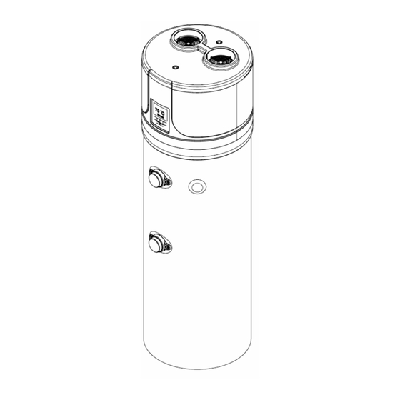
- Page 8 PARTS NAMES NOTE All the pictures in this manual are for explanation purpose only. They may be slightly different from the heat pump water heater you purchased ( depend on the model ). Please refer to the real sample instead of the pictures of this manual.
-
Page 9: Installation Of Heat Pump
INSTALLATION OF THE HEAT PUMP Choose a place Do not install this equipment indoor. If installed indoor, may cause overflow, noise or indoor temperature drop which can influence your normal life, please do preventive measures in advance; The place where must have enough space for installation and maintenance; Inlet or outlet wind must have no obstacle and keep strong wind off;... - Page 10 The Movement of Heat Pump This heat pump is heavy and need at least two people to move and install it; Please move the equipment according to the state of leaving factory, and any self transformation is prohibited; Please install protection plate in which heat pump is easier to touch hard objects for purpose of avoiding scratch and deformation;...
- Page 11 If heat pump installed in the basement, indoor or other airtight space, please note exhausting or intake circulation between surrounding air and outdoor air; The air duct total length should be equal or less than 6 meters, and the duct diameter should be equal or more than 150 mm. Products External Dimension Model / Size YT-200TB2...
-
Page 12: Pipe Line Connection
PIPE LINE CONNECTION Pipe Line Connection Diagram Water Pipe Installation Instructions Please don’t use iron pipe connect to heat pump, please use CPVC pipe,PPR pipe or PB pipe; Please according to the drawing shows to install the water pipes,connectors etc.,if the ambient temperature is below 0 C, proper insulation must be taken for the water pipes;... - Page 13 NOTE The relief valve need to be pulled one time every six months for purpose of taking calcium carbonate out and ensuring no obstacle, outlet temperature of drainage port may be high, please be careful; Drainage pipe must be taken measures to keep temperature to prevent pipe from freezing to cause accident.
- Page 14 NOTE When used for the place where the temperature is below 0φφIf installed the heat pump outdoor, please take measures to protect water pipe according to local minimum temperature to prevent frozen or damage water pipe. Air Duct Installation Instructions Scheme 2 It is recommended to install unit by this way in the winter where there is other heat source in the room.
-
Page 15: Connection Of Electric
The resistance of duct will decrease air-flow-rate,which will lead to capacity of unit decreased, the duct total length should be no more than 6m or the maximum static pressure should within 20Pa, and the quantity bending should be no more than 3; For unit air outlet with duct, when unit operating, condensate will be generated around outside of duct, please pay attention to the drainage work, we suggest to wrap the thermal insulated layer around outside if the duct;... - Page 16 Power Specification Model / Item Power supply The finest wire diameter (mm Leakage protection device Manual switch (A) Size (continuous Ground wire length ≤ 30m) YT-200TB2 ≤6 YT-250TB2 220V/50Hz YT-300TB2 Capacity Fuse Below 30mA 0.1sec YT-300TB2 ≥2.5 ≥20 ≥Φ1.0mm Remark: Please directly connect power supply wire with user’s plug when use the heat pump. Leakage Protection WARNING The external power supply box must be installed leakage protection device based on above figure for...
- Page 17 Electric Wiring Diagram...
-
Page 18: Method Of Application
METHOD OF APPLICATION When using the unit, please operate to the following order: Feeding water: when use the unit for the first time (or reuse it after the tank is empty ), before connect the unit with power, please make sure the tank is full of water. Water feeding method (as below picture) Open the cold water inlet valve and hot water outlet valve. -
Page 19: Controller Instruction
CONTROLLER INSTRUCTION Features Operating condition Main function Voltage:220V~±10%,50Hz±1Hz. Display the water temperature and setting temperature, and also can § § Ambient temperature: -7~+43°C query the coil temperature, ambient temperature and exhaust tempe- § Storage temperature: -20~+70°C rature and so on. §... - Page 20 Name Symbol Function 1. On/off key (hold for 1 second) 2. Return key On/off key 3. Escape key 4. Unlock key (hold for 3 seconds) 1. Setting the clock, press the key will enter into clock setting interface, and then press one time to switch the hour and minute area 2.
- Page 21 Symbol Status Meaning Not bright Heat pump OFF or not in heating mode Light up In heating mode Light up Heating element ON Flash for 1s Run in Boost mode Flash for 2s Run in sterilization mode Flash WIFI distribution network Light up WIFI connect successfully Light up...
- Page 22 Symbol Status Meaning Light up Low fan speed Flash for 1s Ventilation mode: high fan speed Flash for 2s Ventilation mode: low fan speed Display Error code display Light up Timer ON Display In timing ON period Flash Setting timing ON Display In timing OFF period Flash...
- Page 23 In HYB1 mode, the controller will display „ „, in this mode, heat pump and electric heating rununtil the water tempe- rature reach at 60°C, when water temperature up to 60°C, heat pumpwill stop running, electric heating go on heating until the water temperature up to thesetting temperature (if the set value more than 60°C).
- Page 24 Forced defrosting: When the controller is in the normal display mode and the heat pump is ON. Press „M” and „ ” buttons together for more than 5 seconds to activate or deactivate the „Forced Defrost” function. The symbol „ „...
- Page 25 OPERATION PARAMETER QUERY When power on, press „ ” or „ ” button for 3 seconds, will enter into status query interface, press „ ” or „ ” button to query each status; Press „ „ button will exit status query interface. Name Note Fluorine Cycle/Water Cycle system...
-
Page 26: Wifi Function Instruction
WIFI FUNCTION INSTRUCTION When connecting Wi-Fi, the symbol „ „ will flash, when connect Wi-Fi successfully, the symbol „ „ will light up, disconnect Wi-Fi, the symbol „ „ not light up. Press and hold the two keys for 5s, enter into manual intelligent distribution network connection by manual 1. - Page 27 2. Sign up After installing the app, press the „ „ icon and open the Smart Life app, if there is no account, should sign up at first time, refer to following process: STEP 3 STEP 1 STEP 2 STEP 4 STEP 5...
- Page 28 3. Log in After signing up, log in the application refer to following process: STEP 1 STEP 2 Input account and password and log in 4. Create home After signing up, should create „ home „, refer to following process: Home Management →...
- Page 29 2. Connect the WIFI 1) Press and hold the two keys for 5s, enter into manual intelligent distribution network connection, within 3 minutes, wait for connecting, the symbol „ „ will flash, after three minutes, exit connecting automatically if failed in connecting.
- Page 31 3. Operation 1) Operation interface Shows error code Shows set temp. + - key Set temp. Shows water tank temp. ON/OFF Timer setting...
- Page 32 2) Operation interface Or move the circle to change the temp. setting Press - or + to change the water tempe- rature setting 3) Set timer Press...
- Page 33 Set time Repeat Notice On / Off Mode Set temp.
- Page 34 If want to cancel the timer, press and hold it, until shows confir- ming option If want to add more timer, press below “Add Schedule” key to set the timer as per above 4) Others operation Modify the device name and location Check device information Offline Notification...
-
Page 35: Pilot Run Of Heat Pump
PILOT RUN OF HEAT PUMP Please confirm the followings before pilot run of heat pump The heat pump has been finished well; Assemble pipe and wire are all correct; Drain water is smooth; Insulation materials are complete; Ground wire is installed well; Power voltage is equivalent to rated voltage of heat pump;... -
Page 36: After-Sale Service
II. Error & Approaches Error Reason Approach The plug is not plugged properly. The temperature controller is on the lowest Plug in properly. The outlet water is cold; temperature control state; Set the temperature The screen is dark The temperature controller is damaged; of the controller in higher state. - Page 37 Brook House, Dunmurry Industrial Estate, Dunmurry, Belfast, Co. Antrim, BT17 9HU T: 028 9061 6505 M: hello@brookvent.co.uk brookvent.co.uk...
Need help?
Do you have a question about the Airtherm Aqua 1.2 200L and is the answer not in the manual?
Questions and answers