Advertisement
Quick Links
GIGABIT
SWITCH
Q
I
I N D U S T R I A L
uick
nstallation
Introduction
IGS-C3082GP Series are managed redundant ring Ethernet switch with up
to 8x10/100/1000 Base-T(X) ports and 2x100/1000Base-X, SFP socket
which is specifically designed for the toughest. IGS-C3082GP Series
support wide operating temperature from -40° C to 75° C which can fulfill
most of the requirement of operation environment. Therefore, the IGS-
C3082GP Series switch is one of the most reliable choices for highly-
managed Ethernet application.
Package Contents
The device is shipped with the following items. If any of these items is missing
or damaged, please contact your customer service representative for
assistance.
Contents
Pictures
Number
IGS-C9082GP
or
IGS-C9042GP
CD Card
DIN-rail Kit
Console Cable
QIG
Preparation
Before you begin installing the switch, make sure you have all of the package
contents available and a PC with Microsoft Internet Explorer 6.0 or later, for
using web-based system management tools.
Safety & Warnings
Elevated Operating Ambient: If installed in a closed or multi-unit rack
assembly, the operating ambient temperature of the rack environment may be
greater than room ambient. Therefore, consideration should be given to
installing the equipment in an environment compatible with the maximum
ambient temperature (Tma) specified by the manufacturer.
Reduced Air Flow: Installation of the equipment in a rack should be such
that the amount of air flow required for safe operation of the equipment is
not compromised.
Mechanical Loading: Mounting of the equipment in the rack should be
such that a hazardous condition is not achieved due to uneven mechanical
loading.
Circuit Overloading: Consideration should be given to the connection of the
equipment to the supply circuit and the effect that overloading of the circuits
might have on overcurrent protection and supply wiring. Appropriate
consideration of equipment nameplate ratings should be used when addressing
this concern.
Q I G
IGS-C9082GP Series
IGS-C3082GP Series
G
uide
Dimension
IGS-C3082GP
IGS-C3042GP
X 1
X 1
X 1
X 1
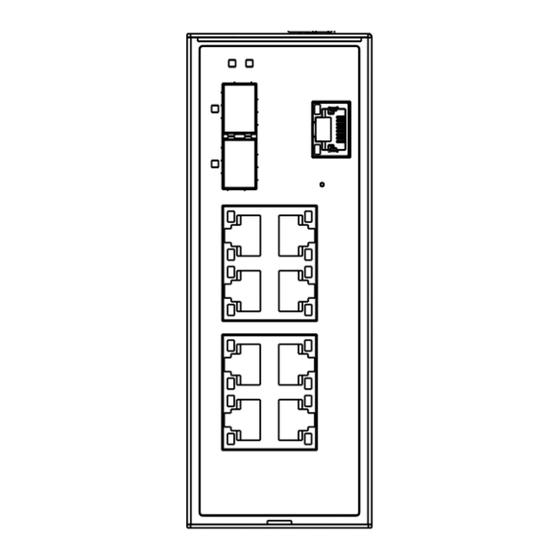
Panel Layouts
IGS-C3082GP
X 1
Front View
1
2
3
4
5
6
1. PWR indicators
2. Ring status LED
3. Link/Act LED for Gigabit SFP ports
4. Gigabit SFP ports
5. Gigabit LAN ports
6. Link/Act LED for Gigabit LAN ports
7. Reset button
8. Console port
Warning [AVERTISSEMENT]
!
Take into consideration the following guidelines before wiring the device.
[Tenez compte des directrices suivantes avant de câbler l'appareil.]
1. Terminal block is mating with Plug and suitable for 12-24AWG. Torque value 4.5 lb-in.
[Le bornier est compatible avec les connecteurs et convient pour 12-24AWG. Valeur de couple 4,5 lb-in.]
2. The temperature rating of the input connection cable should higher than 105°C
[La température de service nominale du câble d'entrée doit être supérieure à 105 °C]
3. Use Copper Conductors Only.
[Utilisez uniquement des conducteurs en cuivre.]
* Indoor use and pollution degree II, it must be wiped with a dry cloth for clean up the device and label.
* Utilisation en intérieur et degré de pollution II, il faut l'essuyer avec un chiffon sec pour nettoyer l'appareil et son étiquette.
* Do not block air ventilation holes.
* Ne bouchez pas les orifices de ventilation.
* If the equipment is used in a manner not specified by the manufacturer, the protection provided by the equipment may
be impaired."
* Si l'appareil est utilise d'une maniere non specifiee par le fabricant, la protection qu'il apporte peut se voir diminuee.
* Shall be mounted in the Industrial Control Panel and ambient temperature is not exceed 75 degree C
* doit être monté dans le panneau de commande industriel et la température ambiante ne doit pas dépasser 75 degrés C.
1907-xxxxxxxxxxxxxxxxxxxx
Unit =mm (Tolerance ±0.5mm)
54.3
108.3
35.0
22.0
54.3
108.3
35.0
22.0
IGS-C3042GP
Top View
Front View
Top View
1
2
3
8
8
7
4
7
1
2
1
1. Ground wire
1. Ground wire
5
2. Terminal blocks: PWR1,
2. Terminal blocks: PWR1,
6
PWR2
PWR2
1. PWR indicators
2. Ring status LED
3. Link/Act LED for Gigabit SFP ports
4. Gigabit SFP ports
5. Gigabit LAN ports
6. Link/Act LED for Gigabit LAN ports
7. Reset button
8. Console port
PRINTED ON RECYCLED PAPER
Industrial Managed Gigabit Switch
Installation
DIN-rail Installation
Step 1: Slant the switch and screw the Din-rail kit onto the back of the switch, right in
the middle of the back panel.
Step 2: Slide the switch onto a DIN-rail from the Din-rail kit and make sure the switch
clicks into the rail firmly.
Network Connection
The switch provides standard Ethernet ports. According to the link type, the switch uses
CAT 3,4,5,5e UTP cables to connect to any other network devices
switches, routers, or hubs). Please refer to the following table for cable specifications.
Cable Types and Specifications:
Cable
Type
10BASE-T
Cat. 3, 4, 5 100-ohm
100BASE-TX
Cat. 5 100-ohm UTP
1000BASE-T
Cat. 5 / Cat. 5e 100-ohm UTP
For pin assignments for different types of cables, please refer to the following
2
tables.
10/100 Base-T(X) RJ-45 Port
Pin Number
Assignments
1
TD+
2
TD-
3
RD+
4
Not used
5
Not used
6
RD-
7
Not used
8
Not used
10/100 Base-T(X) MDI/MDI-X
Pin Number
MDI port
MDI-X port
1
TD+(transmit)
RD+(receive)
2
TD-(transmit)
RD-(receive)
3
RD+(receive)
TD+(transmit)
4
Not used
Not used
5
Not used
Not used
6
RD-(receive)
TD-(transmit)
7
Not used
Not used
8
Not used
Not used
Note: "+" and "-" signs represent the polarity of the wires that make up each wire pair.
Version 1.0
(PCs, servers,
Max. Length
Connector
UTP 100 m (328 ft)
RJ-45
UTP 100 m (328 ft)
RJ-45
UTP 100 m (328 ft)
RJ-45
1000Base-T RJ-45 Port
Pin Number
Assignment
1
BI_DA+
2
BI_DA-
3
BI_DB+
4
BI_DC+
5
BI_DC-
6
BI_DB-
7
BI_DD+
8
BI_DD-
1000Base-T MDI/MDI-X
Pin Number
MDI port
MDI-X port
1
BI_DA+
BI_DB+
2
BI_DA-
BI_DB-
3
BI_DB+
BI_DA+
4
BI_DC+
BI_DD+
5
BI_DC-
BI_DD-
6
BI_DB-
BI_DA-
7
BI_DD+
BI_DC+
8
BI_DD-
BI_DC-
Quick Installation Guide
Advertisement

Summary of Contents for Origin IGS-C3082GP Series
- Page 1 Introduction IGS-C3082GP DIN-rail Installation IGS-C3082GP Series are managed redundant ring Ethernet switch with up Step 1: Slant the switch and screw the Din-rail kit onto the back of the switch, right in to 8x10/100/1000 Base-T(X) ports and 2x100/1000Base-X, SFP socket the middle of the back panel.
- Page 2 Version 1.0 GIGABIT IGS-C3082GP Series SWITCH Industrial Managed Gigabit Switch I N D U S T R I A L uick nstallation uide Specifications Console Port Pin Definition Follow the steps to set up the switch: ORing Switch Model IGS-C3042GP...
Need help?
Do you have a question about the IGS-C3082GP Series and is the answer not in the manual?
Questions and answers