Table of Contents

Related Manuals for Tekbox TBMR-110M

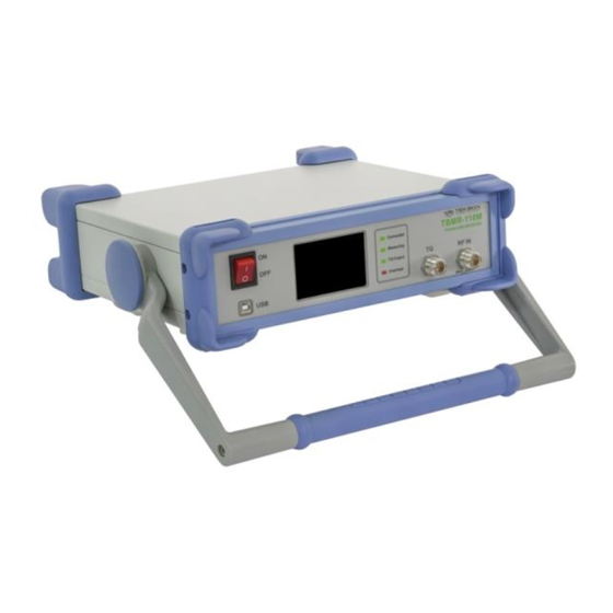
Summary of Contents for Tekbox TBMR-110M
- Page 1 TBMR-110M DC - 110 MHz high speed EMI-Analyzer Quick Reference Manual Rev.1.0 www.tekbox.com Tekbox Digital Solutions Vietnam Co. Ltd. Factory 4, F4, Lot I-3B-1, Saigon Hi-Tech Park, Tan Phu Ward, District 9, Ho Chi Minh City, Vietnam...
-
Page 2: Table Of Contents
Contents Introduction to the TBMR-110M EMI analyzer ................3 Safety ............................3 Main Features .......................... 3 Application Overview ......................5 System Requirements......................5 Packaging List .......................... 5 Unpacking and Preparations for First Use................5 Software Installation ....................... 7 First Power - On ........................8 Operation ............................ -
Page 3: Introduction To The Tbmr-110M Emi Analyzer
1 Introduction to the TBMR-110M EMI analyzer 1.1 Safety Before using the instrument, carefully read the safety chapters in the TBMR-110M Operation Manual! Warning: Manual mains voltage selection is required Ensure that the mains voltage selector switch is set correctly to avoid damaging the instrument. - Page 4 • Tracking Analyzer DC - 110 MHz Linear and logarithmic sweep -50 dBm to 0 dBm adjustable TG power 120 dB dynamic range Use of power correction file and level correction file Quick load of predefined setups. • Oscilloscope 250 MS/s, DC - 110 MHz 1 ns/DIV to 1 s/DIV horizontal resolution Interpolated sampling up to 4 GS/s Real-time Sampling up to 250 MS/s, 14 Bit...
-
Page 5: Application Overview
1.4 System Requirements The TBMR-110M system software requires a Microsoft Windows(R) 7 (SP1) 64 Bit, Windows 10 (R), Windows 11 (R) compatible computer with an USB 2.0 high speed interface, about 200 MB free disk space, an Intel Core I5 (R) processor with 3 GHz clock speed (or equivalent) and 4 GB of system memory as minimum recommendation. - Page 6 Carefully unpack the shipping box an remove the packaging material. Carefully check your TBMR-110M for any shipping damage. Check if the receiver´s AC mains supply voltage matches the power grid voltage in your country. To do so, turn the analyzer around and have a look at the rear panel.
-
Page 7: Software Installation
Plug the supplied USB Stick into the USB port of the PC which you want to connect to the receiver and open the software folder. Start the "Setup_TBMR-110M_Vxxx.exe" file as administrator. The Installer will guide you through the rest of the Installation. Figure 1-7 TBMR-110M SW installer window The Installer will install both the receiver software as well as the device driver. -
Page 8: First Power - On
TFT screen and the green LED "Connected" will light up on the analyzer front panel. The display can also be configured to display the measurement graphs. In the device manager a new device folder "TekBox" should appear: Figure 1-9 Windows Device Manager indicating that the receiver is successfully connected If the analyzer does not connect successfully to your PC, please verify the USB connection. - Page 9 If the device driver is properly loaded, the "Connected" - box is checked and the receiver is ready for operation. For a first test, click on the EMI Analyzer icon. Following window will pop up: Figure 1-11 Main EMI analyzer window Now click on the Import Icon on the top of the window and navigate to a project file folder, e.g.: CISPR 32_EN55032_V1_3\CN Select a project file, e.g.:...
- Page 10 Without signal applied, after a few seconds of operation, the diagram window should show a result similar to the figure shown below: Figure 1-14 Measurement result; no signal connected to the RF-input Congratulations! You have made your first EMI measurement with the TBMR-110M.
-
Page 11: Operation
Exceeding the maximum RF input power or voltage will damage the instrument! 2.2 Starting the Software The TBMR-110M software can be launched by either double-clicking the desktop icon or by selecting it from the TekBox Program folder. The following window will appear when the software starts:... - Page 12 The System Menu contains following sub items: • Select Home Path This item let you select a different home path folder for data and setup storage. Default is: <UserProfile>/TekBox/TBMR-110M • System Test This item will perform several hardware tests and display version information. An unchecked test checkbox will indicate a hardware malfunction.
-
Page 13: Emi Analyzer Application
• Read Calibration Saves the analyzer´s calibration data to the computer • Write calibration Loads a calibration file from the computer and stores it on the analyzer. Needs an analyzer power cycle to be activated. Unlock Calibration Entering the password will unlock the calibration functionality and enable the System Service item. The default password is a zero-string, which means just press <Enter>. - Page 14 EMC measurements can be configured manually, however all conducted emission tests of major standards are already implemented. First load a suitable EMI Project from a pre-defined list. The projects are sorted in EMI standard sub-directories and contain all relevant emission limits. The standards are implemented as text files, very similar to the EMCview project file standard.
- Page 15 Always use an external attenuator/limiter, if you test an unknown EUT / source. Levels above the given input power / voltage rating (even for short bursts) will trigger an overload condition only during an active measurement. Warning: Maximum RF input power handling The maximum allowed RF input power is +30 dBm (1 W or 7V) continuous power.
- Page 16 frequency spectrum e.g. during warm up. This peak-search will ensure that the highest peak will be detected in a window of n x RBW/4. The factor n can be adjusted. Peak filter mode: • none No peak filter technique is used, every violation of the peak threshold is re-measured for each point of the current sweep.
- Page 17 TBMR-110M software automatically loads suitable compensation files, when loading a project. Compensation files for most Tekbox transducers and for a few third-party transducers are already pre-installed. Tekbox typically releases compensation files for new products on the product websites. These can be downloaded and...
- Page 18 Setup 3 Tab Figure 2-10 EMI Analyzer window; Setup 3 Tab; limit files of the selected project automatically loaded Setup Tab 3 top does allow for single frequency spot measurement. If some peak seems suspicious or another not covered frequency band is of interest this is a convenient way to measure a single frequency location. Just enter the desired frequency value and press the "Play"...
- Page 19 EMCview, if you want to create more detailed reports. Furthermore, you can configure the appearance of the EMI analyzer after startup. When using any TBMR-110M application, it is recommended to arrange the app window and graph window according to personal preference and configure the “Startup Load Settings”...
-
Page 20: Spectrum Analyzer Application
2.4 Spectrum Analyzer Application Figure 2-13 Example; screen shot of the spectrum analyzer application The spectrum analyzer application has essentially the same functionality as most traditional spectrum analyzers. However, it is unique in its measurement capability at low frequencies. Frequency / Amplitude / Resolution Bandwidth Tab Figure 2-14Frequency menu When modifying Start- and Stop - Frequency settings, ensure that the entered value of the start frequency is lower than the stop frequency or vice versa. - Page 21 When adjusting the Reference Level, it is best to leave the "Manual" checkbox unchecked. The attenuation will be automatically matched to the reference level. Be mindful of how the Attenuation / Gain settings affects the TBMR-110M's maximum RF input power rating. Scaling is utilized for compensating, when employing external attenuators or transducers.
- Page 22 Figure 2-16 Bandwidth menu The Resolution Bandwidth refers to Gaussian filters specified over their 3dB bandwidth. When manually decreasing resolution bandwidth, the number of measured frequency-points each sweep increases in order to avoid spectrum gaps between adjacent frequency-points. The number of frequency points per sweep is displayed in the lower right corner of the bandwidth menu.
- Page 23 Check the “Custom Unit” box to select units which are not listed in the left column of the window. To display special results, such as for example dBµW/Hz or nV/Sqrt(Hz), use an equation for trace arithmetic. • Logarithmic Changes the amplitude axis between linear and logarithmic •...
- Page 24 Settings Tab Figure 2-24 Settings Menu Configure the appearance of the spectrum analyzer after startup. When using any TBMR-110M application, it is recommended to arrange the app window and graph window according to personal preference and configure the “Startup Load Settings” to “Last”.
-
Page 25: Tracking Analyzer Application
NIST- calibrated spectrum analyzer to calibrate the tracking generator. A separate calibration instruction is available upon request from Tekbox. Figure 2-25 Settings Menu 2.5 Tracking Analyzer Application Figure 2-26 Scalar network analyzer, DC to 110 MHz, dynamic gain control; example: frequency response of a high-pass filter Application: Characterizing the frequency response of transducers from very low frequencies up to 110 MHz. - Page 26 The implementation of the tracking analyzer is similar to most conventional spectrum analyzers with tracking generator. A coaxial cable connects the tracking generator output with the RF input of the TBMR-110 M for normalization. After normalization, a transducer or other EUT is connected in between tracking generator output and RF-input to measure the frequency response.
-
Page 27: Oscilloscope Application
Restarts the application using a custom configuration. The setup must be found among the saved setups. The name of the setup must be entered manually. If desired, the auxiliary TFT display on the TBMR-110M's front panel can be configured to display graph data. 2.6 Oscilloscope Application... - Page 28 The oscilloscope is useful, when the noise spectrum of an Equipment under Test has to be correlated with the time domain. In contrary to a typical oscilloscope, the implementation in the TBMR-110M lacks a high impedance input and input protection.
- Page 29 Always use an external attenuator/limiter, if you test an unknown EUT / source. Levels above the given input power / voltage rating (even for short bursts) will trigger an overload condition only during an active measurement. The horizontal resolution can be changed between 1ns/DIV and 1s/DIV. Figure 2-36 Horizontal resolution settings Use the trigger function to synchronize the horizontal sweep at the correct point of the signal.
-
Page 30: Demodulator Application
2.7 Demodulator Application Figure 2-39 Demodulator panel The demodulator application allows to utilize the TBMR-110M to demodulate an RF signal and transfer it to the computers sound card. Any sound processing, recording or analysis software can be used to select the demodulated audio as input signal. - Page 31 FM (frequency modulation) - Demodulator: Figure 2-41 FM Demodulator tab. FM is characterized by its frequency deviation: The FM peak Deviation For narrowband FM the peak deviation is typically +/- 5 kHz (e.g. CB radio) For wideband FM it is typically +/- 75 kHz (e.g. FM radio) Following parameters are measured: •...
-
Page 32: Remote Control Application
110M, not all operation modes of the conventional EMCview (PRO) software are accessible. Launch the EMCview installer provided on the USB stick with the TBMR-110M software. After installation, turn on the TBMR-110M and connect it to the PC, using the supplied USB cable. Launch EMCview and enter the “Connect” menu. -
Page 33: I/Q Data Streaming Application
After completing measurements, go to the “Device” menu, and select “Disconnect” and then “Stop Receiver App”. EMCview is ready to be shut down now. If you forget to press the “Stop Receiver App” button and wish to use the TBMR-110M software, close it using the Windows Task Manager and then launch it normally. -
Page 34: History
The network streaming option can be used as a data source in GNU-Radio: Figure 2-49 Simple FM Demodulator in GNU-Radio using the TBMR-110M as data source. For the data source a UDP source is selected and the IP address and port settings must match the parameters in the streaming application GUI.
Need help?
Do you have a question about the TBMR-110M and is the answer not in the manual?
Questions and answers