
Related Manuals for Grizzly G0882


Summary of Contents for Grizzly G0882
- Page 1 MODEL G0882 200A MIG/MMA WELDER OWNER'S MANUAL (For models manufactured since 08/19) 4009939...
- Page 2 This manual provides critical safety instructions on the proper setup, operation, maintenance, and service of this machine/tool. Save this document, refer to it often, and use it to instruct other operators. Failure to read, understand and follow the instructions in this manual may result in fire or serious personal injury—including amputation, electrocution, or death.
-
Page 3: Safety Instructions For Machinery
SAFETY For Your Own Safety, Read Instruction Manual Before Operating This Machine The purpose of safety symbols is to attract your attention to possible hazardous conditions. This manual uses a series of symbols and signal words intended to convey the level of impor- tance of the safety messages. - Page 4 WEARING PROPER APPAREL. Do not wear FORCING MACHINERY. Do not force machine. clothing, apparel or jewelry that can become It will do the job safer and better at the rate for entangled in moving parts. Always tie back or which it was designed. cover long hair.
- Page 5 Additional Safety for Plasma Cutters and Welders WELDING FUMES. Breathing welding fumes can PROTECT BODY FROM ARC BURNS, SPARKS, cause suffocation or poisoning without warning. AND SPATTER. Wear correct and approved eye, Keep your head out of welding fumes. Use ade- ear, and body protection.
-
Page 6: Additional Sources For Welding Codes And Standards
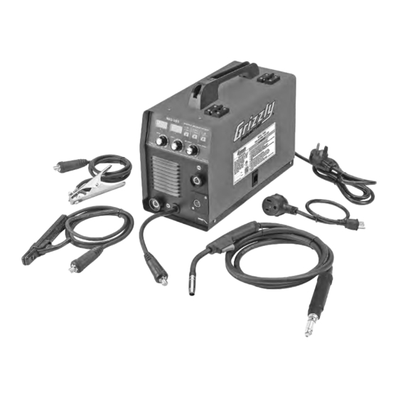
Additional Sources for Welding Codes and Standards American Welding Society, 550 N.W. LeJeune Road, Miami, FL 33126, (305) 443-9353, Website: www.aws. org. —Safety in welding, Cutting, and Allied Processes, ANSI Standard Z49.1 —Recommended Safe Practices for the Preparation for Welding and Cutting of Containers and Piping, AWS F4.1 National Fire Protection Association, P. - Page 7 Customer Service #: (570) 546-9663 · To Order Call: (800) 523-4777 · Fax #: (800) 438-5901 MODEL G0882 200A MIG/MMA WELDER Product Dimensions: Weight ..................................... 30 lbs. Width (side-to-side) x Depth (front-to-back) x Height ..................9 x 18 x 15 in.
- Page 8 Features: IGBT Technology Improves Efficiency Adjustable Amperage and Voltage Control with Digital Display Arc Force and Wave Control Gas Test Button Quick Wire Feed Button Capable of Welding Steel, Stainless Steel, and Carbon Steel Accessories: Brush/Chipping Hammer Gas Regulator 0.030 in. & 0.035 in. Tips Plug Adapter for 120V...
-
Page 9: Power Supply
POWER SUPPLY Availability Circuit Information Before installing the machine, consider the avail- A power supply circuit includes all electrical ability and proximity of the required power supply equipment between the breaker box or fuse panel circuit. If an existing circuit does not meet the in the building and the machine. -
Page 10: Extension Cords
Circuit Requirements for 115V Adaptor This machine can be converted to operate on a power supply circuit that has a verified ground Serious injury could occur if you connect and meets the requirements listed below. (Refer machine to power before completing setup to Voltage Conversion instructions for details.) process. -
Page 11: Installation
INSTALLATION FILLER WIRE The machine is delivered with the welding gun connected to + pole making it suitable for steel solid wire welding without adjustments. Changing the feed roll groove The feed roll groove is factory set for welding filler wires of 0.8-1.0 mm diameter. The feed roll groove must be changed if you use 0.6 mm thick filler wire. - Page 12 5. Open the pressure control lever which then opens the feed gear. 6. Thread the wire through the wire's rear guide to the gun's wire guide. 7. Close the feed gear and fasten it with the pressure control lever. Make sure that the wire runs in the feed roll groove.
-
Page 13: Operation
OPERATION Reversing polarity Some filler wires are recommended to be welded with the gun in the - pole. So the polarity should be reversed. Check the recommended polarity from the filler wire package. 1. Disconnect the machine from the mains. 2. -
Page 14: Maintenance
MAINTENANCE When servicing the machine, its utilization degree and environmental circumstances should be taken into account. If you use the machine appropriately and service it regularly, you will spare yourself from unnec- essary malfunctions. CAUTION! Disconnect the machine from the mains before handing the electrical cables. DAILY MANITENANCE Remove welding spatters from the welding gun's tip and check the condition of the parts. - Page 15 Cleaning the wire guide Pressure of the feed rolls removes metal dust from the filler wire's surface which then finds its way to the wire guide. If the wire guide is not clean, it gradually clogs up and causes wire feed malfunctions. Clean the wire guide in the following manner: 1.
- Page 16 MACHINE ID LABEL V2.08.19 P0882012 WIRE SPOOL HOLDER We do our best to stock replacement parts when possible, but we cannot guarantee that all parts shown are available for purchase. Call (800) 523-4777 or visit www.grizzly.com/parts to check for availability.
-
Page 17: Troubleshooting
SERVICE Review the troubleshooting and procedures in this section to fix or adjust your machine if a problem devel- ops. If you need replacement parts or you are unsure of your repair skills, then feel free to call our Technical Support at (570) 546-9663.
Need help?
Do you have a question about the G0882 and is the answer not in the manual?
Questions and answers