Table of Contents
Advertisement
Quick Links
Address: 9100, Côte-de-Liesse, Lachine QC H8T 1A1
Tel: 1-800-663-3130
GARAGE DOOR operator
Models 9367 / 9367M
For Residential Use Only
Before installation, write down the serial number and purchase date:
(The model number is labeled on the plastic cover with light socket of your operator).
Serial # _ _ _ _ _ _ _ _ _
Purchase Date _ _- _ _- _ _ _
Version No.:MEN-005-C
1
Advertisement
Table of Contents

Summary of Contents for DorLyft 9367
- Page 1 Address: 9100, Côte-de-Liesse, Lachine QC H8T 1A1 Tel: 1-800-663-3130 GARAGE DOOR operator Models 9367 / 9367M For Residential Use Only Before installation, write down the serial number and purchase date: (The model number is labeled on the plastic cover with light socket of your operator).
-
Page 2: Table Of Contents
Owner’s Manual Before installation, please read this manual and instructions carefully! The Photo eye system must be installed. Routine maintenance of the operator according to this manual to ensure safe operation. Please keep the manual in your sight near the garage door. TABLE OF CONTENTS Introduction…............3-4 15. -
Page 3: Introduction
INTRODUCTION Safety Symbols This garage door operator has been tested and manufactured to provide safe service . Please install, handle, maintain, and check in strict compliance with the instructions and warnings used in this owner’s manual. The following Safety Symbols used in this manual will warn you the possibility of serious injury or death if you do not operate in accordance with the warnings attached. - Page 4 IMPORTANT INSTALLATION INSTRUCTIONS WARNING To prevent any possible SERIOUS INJURY or DEATH: 1. Read and follow all installation instructions. 2. Always call a professional qualified door technician to make repairs to garage door cables, spring assemblies, and other hardware before installing the operator.
-
Page 5: Operator Contents And Tool
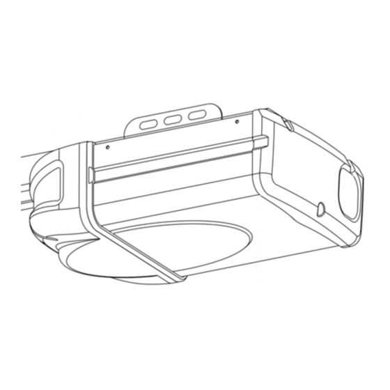
Operator contents and tools: Models 9367 / 9367M PACKING LIST Packing case #1:Door opener, Installation Instructions #2:Light Lens, Wall Control Panel #3:Hardwares, Photo Eye Sensors, Three-key Remote Control Note:Door arm sections are packaged at the bottom of the box. - Page 6 A、Header bracket J、Garage door operator B、Pulley assembly K、“U” rail clips(2) C、 Door bracket L、Photo eye sensors D、 Curved door arm M、Chain/Belt E、Straight door arm N、 Sprocket and sprocket holder assembly F、 Trolley assembly O、Wall Control G、Emergency release rope and knob P、Safety labels and literature H、One-Piece Rail(Or Sectional Rail) Q、Rail connectors assembly...
- Page 7 The tools illustrated below may be used during installation and adjustment of your operator: For future reference, the following parts should be pre-installed in the rail. One-piece Rail...
- Page 8 Three-pieces Sectional Rail Square neck bolt M8(8) Flange nut M8(8) Rail connector B (2) Rail connector A (2) Front rail End rail Center rail...
- Page 9 Three-piece Sectional Rail Assembly 1、Remove the three rail sections and place them on floor. Center rail Top rail End rail 2、Rail connectors installation. Q、 Rail connectors assembly 3、Spread carefully the chain/belt straight inside the rail. Check to be sure the chain is not twisted. NOTE: Make sure the chain engage the 10-tooth sprocket as shown.
- Page 10 4、Screw and lock washer installation. NOTE:If the chain(or belt) is too tight or too loose, please turn the outer nut to adjust the tension. Three-piece Sectional Rail...
- Page 11 F 、 Trolley Assembly (Pre-assembled and packed in the carton for operator) Locking Holes · Note: the trolley SHOULD be away from locking holes. Belt Belt Belt Connector Chain Chain Chain Connector...
- Page 12 Hardware H2 Shouldered H3 Hex Nut M8(6) H1 Shouldered shaft, short Φ8×30 (2) shaft, long Φ8×80 (1) H6 Cross recessed tapping H4 Hex Bolt M8×20(10) H5 Circle Pin Φ2×25(3) screw M6×30 (4) H7 Lag Screw M8×50 (6) H8 Self-drilling H9 Spring washer M8 (4) ScrewM6×25 (4) Hanging bracket Screw M4×30 (2)
-
Page 13: Installation Steps
INCLUDED ACCESSORIES Wall Control Panel Remote Control Photo Eye Sensors W221 INSTALLATION STEPS Do not run the garage door operator until instructed. CAUTION To prevent INJURY from pinching, keep hands and fingers away from the joints while assembling the rail 1、Adjust the chain or belt 1.1 To increase the tension and tighten the chain, turn the tension nut clockwise with adjustable wrench until the nut is spaced properly from... -
Page 14: Connect The Rail To The Operator
2、Connect the rail to the operator CAUTION To avoid SERIOUS damage to garage door operator, use ONLY those bolts mounted in top of the operator. 2.1 Position operator with light facing towards the garage door. Rest operator head on cardboard or protective surface on floor so operator does not get scratched. Chassis side of operator facing up. -
Page 15: Install The Header Bracket
Align the Shaft with sprocket hole, if necessary please pull chain/belt to a better position to install. 3、Install The Header Bracket WARNING To reduce any possible SERIOUS INJURY or DEATH: · Header bracket MUST be fastened to structural support on header Wall or ceiling, otherwise the reversing safety system may not work. -
Page 16: Ceiling
Optional ceiling Unfinished mount for ceiling Header bracket Structural support Header wall... -
Page 17: Connect The Rail To The Header Bracket
4、Connect the Rail to the Header Bracket Align the rail to the header bracket, fasten with the bolts and nuts (H1) (H2) as shown below. HARDWARE Circle Pin Φ2×25(1) H1 Shouldered shaft, long Φ8×80 (1) 5、Attach the garage door operator to the ceiling 5.1 Elevate the operator onto a ladder. - Page 18 H4 Hex Bolt M8×20(4) H7 Lag Screw M8×50 (2) H3 Hex Nut M8(4) 5.4 The garage door operator must be 5.3 On finished ceilings, use the lag aligned with the hanging bracket. The screws (H7) to fasten a hanging distance from each side of the garage bracket (not provided) to the structural door operator to the structural supports before installing the garage...
-
Page 19: Install The Door Bracket
5.6 Fasten the end of each hanging 5.5 Cut the hanging brackets to bracket to the bracket on the measured lengths. ceiling. 5.7 Fasten the hanging bracket on the chassis of garage door operator with bolts (H4),and nuts (H3). 5.8 Open and close the door manually. -
Page 20: Attach The Door Arm
6.1 Keep the door in the closed position. 6.2 Align the door bracket to the center line of the top section 2” to 4” below the top edge of the door. Mark mounting points. 6.3 Drill 3/16" fastening holes, Secure the door bracket by using the four self-threading screws (H8). - Page 21 Pull the emergency release to move the trolley to the locking holes. Connect the straight door arm to the trolley by using the shouldered shaft (H2).Attach the shouldered shaft with the cotter pin. (Note: In case of power failure, pull the release handle to move trolley to locking hole, so that the garage door is securely locked ) 7.3 Line up the straight arm and curved arm.
-
Page 22: Install Light Bulb
NOTE: If the door arm is hanging down too far, please cut the extra part from the end. 8、Install light bulb WARNING To avoid possible overheating of the end panel or light socket: · Use ONLY A19 incandescent or compact fluorescent light bulbs. ·... -
Page 23: Knob
9、Install the Emergency Release Cord and Knob WARNING To avoid possible SERIOUS INJURY or DEATH from a falling garage door: If possible, use emergency release to disconnect trolley ONLY when garage door is closed. Deficient springs or unbalanced door could cause an open door falling accident. -
Page 24: Install The Wall Control
10、Install the wall control WARNING Installation and wiring must comply with local building and electrical rules and laws. To avoid any possible SERIOUS INJURY or DEATH : · DO NOT connect the power source at this time. · The wall control should be at a minimum height of 5 feet (1.5 m) from the floor out of reach of children. -
Page 25: Connect The Wall Control To The Garage Door
10.3 If the wires are not connected, 10.4 Mark the location of the 2 holes Connect the white wire to the #3 of back cover of wall control and screw ,connect the red \white drill a 6 mm hole. wire to the #4 screw. 10.5 Insert and tighten screws to 10.6 Snap the wall control secure the back cover of the... -
Page 26: Attach The Warning Labels
5/13” (10mm) SETTING DOWN CODE Note: To connect or disconnect the wires from the terminal, press in the tab with a screwdriver tip. 12、Attach the warning labels 12.1 Attach the warning label firmly near the wall control where people can easily read. -
Page 27: Install The Photo Eye System
13、Install The Photo Eye System WARNING Do not plug the operator in. To avoid SERIOUS INJURY or DEATH from a closing garage door: · Properly install the Photo eye safety system as instructed. The photo eye safety system MUST NOT be deactivated. ·... - Page 28 Infrared beam protection area Photo eye Sensor 6”(15cm) max .above floor 13.1 Install the Photo Eye Sensors(PE-002) The photo eye sensors can be attached to the wall or the floor, The sensors should be no more than 6 inches (15 cm) above the floor. H6 Cross recessed tapping screw M6×30 (4)
- Page 29 NOTE: 1. Draw a line from the floor, no more than 6 inch(15cm). 2. Locate the mounting bracket against the wall as figure, and mark the mounting points, with sensor holder facing each other from left to the right of the door. 3.
-
Page 30: 14. Connect The Operator To Power
14. Connect the operator to power WARNING To prevent electrocution or fire, installation and wiring must comply with all local electrical and building codes. · Please make sure power is NOT connected to the operator. · Make sure the operator is grounded, do not modify the plug. NOTE: Do not use extension cord. - Page 31 To make a permanent connection through the 7/8" hole in the top of the motor unit (according to local code): (1) Make sure power is NOT connected to the operator, and disconnect power to circuit. (2) Open the garage door operator cover and set aside. (3) Remove the attached green ground terminal.
-
Page 32: System
15. Aligning and adjusting the Photo Eye System. Always make sure there is a clear path between sensors. The operator will not run if the sending sensor and receiving sensors are not correctly aiming each other. If the sensors are aligned correctly, the LEDs in both sensors will glow. -
Page 33: Test And Adjustments
Test and Adjustment WARNING · To prevent possible serious injury or death by a closing garage door, Please correctly install reversing safety system and garage door operator. · During installation and test of the operator, make sure no one (particularly children ) near or around the garage door. - Page 34 1.1 Press and hold the SETTING 1.2 Press and hold the UP Button to bring Button until the screen show “1”. the door to the desired open position. SETTING SETTING CODE DOWN DOWN CODE 1.3 Use UP button and Down button to adjust until the desired open position is found.
-
Page 35: Test The Reversing Safety System
2、TEST THE REVERSING SAFET SYSTEM WARNING To prevent possible serious injury or death by a closing garage door, Please correctly install reversing safety system and garage door operator. The garage door must reverse on contact with a 1-1/2" (3.8cm) high object on the floor. -
Page 36: Force Sensitivity Adjustment
3、FORCE SENSITIVITY ADJUSTMENT CAUTION factory default settings can be restored .This programming may only be carried out by a professional installer. 3.1 Adjust The CLOSE force sensitivity a. Press and hold the SETTING Button b. Press and release the DOWN until the screen show the number from Button and the screen show the “... - Page 37 3.2 Adjust The “OPEN” force sensitivity a. Press and hold the SETTING b. Press and release the UP Button Button until the screen show the and the screen show the “∩” number from “1” to “3”. SETTING SETTING DOWN CODE CODE DOWN c.
-
Page 38: System
4、TEST THE PHOTO EYE SAFETY SYSTEM 4.1 While the door is fully opened, lay a box under the door to block infrared light beam. 4.2 Close the door with remote control. The door should not move, and the garage door operator lights will flash three minutes. - Page 39 SAFETY INSTRUCTION IMPORTANT SAFETY INSTRUCTIONS WARNING To reduce the risk of SEVERE INJURY or DEATH: 1. READ AND FOLLOW ALL INSTRUCTIONS. 2. NEVER let children operate or play with garage door controls or remote controls. Keep remote control away from children. 3.
-
Page 40: Wall Control
5、 WALL CONTROL Open/close button Open/Close Button To open and close, press the open/close button Light button LIGHT BUTTON To turn the garage door operator lights on or Lock button off, use the light button. Once the lights are on ,they will stay on until being pressed again or be off after three minutes . -
Page 41: Program The Remote Control
6、PROGRAM THE REMOTE CONTROL 6.1 Press the CODE Button on the setting panel until the screen shows “●”. SETTING CODE DOWN 6.2 Within 10 seconds, press the Button 1 on the remote control , the “●”will turn off. Press the Button 1 again, the “●” will flash and turn off. Now, congratulation! Button 1 SETTING Button 2... -
Page 42: Remote Control Battery Replacement
7. REMOTE CONTROL BATTERY REPLACEMENT AND VISOR CLIP INSTALLATION ① ② ④ ③ 1、Battery replacement. • Unscrew and open the rear cover gently. – Replace the battery with a new one and insert it correctly – Recommended battery type: 3V CR2032 coin battery •assemble the rear cover into place •Tighten the screws. -
Page 43: Delete The Memory
8、DELETE THE MEMORY DELETE ALL MEMORY FROM REMOTE CONTROLS Press and hold the CODE button on SETTING PANEL, the “●” will turn on. Release the CODE button until the “●” turns off. All remote controls are now disabled. To reprogram, refer to Program The Remote Controls. SETTING SETTING CODE... -
Page 44: Maintenance Schedule
9.1 How to use the emergency release: a If possible, keep the door in closed position. b Pull down the emergency release knob and hold. Then carefully open or close the door manually, always take highly cautious when the door is disconnected from the operator because of falling door. -
Page 45: Operator Parts
Operator Parts: DESCRIPTION ACCESSORIES 1. Chassis. 1.Mounting Bracket and the 2. Motor and Hall sensor reversing safety sensors with 3. Transformer wire (PE-002) 4. Logic Control Board 2.Three Keys Wall control 5. Light Lens 3.Remote control 6. Light Socket 7. Light socket fixed board 8. - Page 46 GARAGE DOOR OPERATOR PARTS 5. Light Lens 9.Plastic cover with Logic Control Board 7. Light socket fixed board 6. Light Socket 11. Wiring Board 4. Logic Control Board 10. Cover. 1. Chassis. 8. Plastic cover with 3.Transformer light socket 2. Motor and Hall sensor.
-
Page 47: Troubleshooting
Troubleshooting The screen on setting panel of your operator shows the diagnostic codes. Screen Problem Most likely Solution show Number No closing movement Photo eyes not Check if the photo eye system is properly installed and connected. (refer to Install The and flashing light. - Page 48 Letter The garage door operator Program error If the garage door moves okay, reprogram the will not automatically travel. flashing open and close the door . The light will flash. Number The door cannot move. Low power Have the logic board replaced. The light will flash.
-
Page 49: Limited Warranty
Seaside’s cost. Devices must be sent to DorLyft for service at owner’s expense. This warranty does not apply to damage to the product from negligence,abuse,abnormal usage, misuse, accidents, normal wear or tear or due to failure to follow Seller’s instructions, or arising from...
Need help?
Do you have a question about the 9367 and is the answer not in the manual?
Questions and answers