Table of Contents
Advertisement
Quick Links
SERVICE
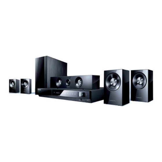
Digital Home Cinema System
HT-C460
Refer to the service manual in the GSPN (see the rear cover) for the more information.
Digital Home Cinema
System
Model Name : HT-C460
Model Code : HT-C460/XAZ
Speaker
PS-C460
Front
PS-FC460
Center
PS-CC460
Rear
PS-RC460
Subwoofer
PS-WC460
Manual
1. Precaution
2. Product Specification
3. Disassembly & Reassembly
4. Troubleshooting
5. Exploded View & Part List
6. PCB Diagram
7. Schematic Diagram
CONTENTS
Advertisement
Table of Contents

Related Manuals for Samsung HT-C460


Summary of Contents for Samsung HT-C460
- Page 1 Digital Home Cinema System Model Name : HT-C460 Model Code : HT-C460/XAZ Speaker PS-C460 Front PS-FC460 Center PS-CC460 Rear PS-RC460 Subwoofer PS-WC460 SERVICE Manual Digital Home Cinema System CONTENTS 1. Precaution 2. Product Specification 3. Disassembly & Reassembly 4. Troubleshooting 5.
- Page 2 Asia asia.samsungportal.com Mideast & Africa mea.samsungportal.com © Samsung Electronics Co.,Ltd. May. 2010 This Service Manual is a property of Samsung Electronics Printed in Korea Co.,Ltd. Any unauthorized use of Manual can be punished under applicable International and/or domestic law.
-
Page 3: Table Of Contents
Contents 1. Precaution 1-1 Safety Precautions ................... 1-1 1-2 Servicing Precautions ..................1-3 1-3 Precautions for Electrostatically Sensitive Devices (ESDs) ......1-4 2. Product Specification 2-1 Product Feature ....................2-1 2-2 Specifications ....................2-2 2-3 Specifications Analysis ..................2-4 2-4 Accessories ......................2-7 3. Disassembly & Reassembly 3-1 Overall Disassembly &... - Page 4 Contents 7. Schematic Diagram 7-1 Overall Block Diagram ..................7-1 7-2 FRONT ......................7-2 7-3 KEY ........................7-3 7-4 MAIN ........................7-4 7-5 MPEG.......................7-5 7-6 MICOM ......................7-6 7-7 AV I/O .......................7-7 7-8 AMP .........................7-8 7-9 Audio AMP-1 ....................7-9 7-10 Audio AMP-2 ....................7-10 7-11 Audio AMP-3 ....................
-
Page 5: Precaution
1 and 5.2 megohms. If there is no return path, the measured resistance should be “infinite.” If the resistance is outside these limits, a shock hazard might exist. See Fig. 1-2 Samsung Electronics... - Page 6 . Use replacement components that have the same ratings, especially for flame resistance and dielectric strength specifications. A replacement part that does not have the same safety characteristics as the original might create shock, fire or other hazards. Samsung Electronics...
-
Page 7: Servicing Precautions
8. Always connect a test instrument’s ground lead to the instrument chassis ground before connecting the positive lead; always remove the instrument’s ground lead last. First read the “Safety Precautions” section of this manual. If some unforeseen circumstance creates a conflict between the servicing and safety precautions, always follow the safety precautions. Samsung Electronics... -
Page 8: Precautions For Electrostatically Sensitive Devices (Esds)
8. Minimize body motions when handling unpackaged replacement ESDs. Motions such as brushing clothes together, or lifting a foot from a carpeted floor can generate enough static electricity to damage an ESD. Samsung Electronics... -
Page 9: Product Specification
- Defect Disc Recovery Solution can deliver a clear picture despite of scratches or other defects on the disc. Touch Sensor - Emotional values by using the touch sensor button Portable Connection - Easy Connectivity - Walkman, ipod, MD etc. DRM Free - Connect with any kinds of Portable Audio device - Stereo Input in Front Samsung Electronics... -
Page 10: Specifications
Pb: 0.70 Vp-p (75Ω load) VIDEO/ HDMI 1080p, 1080i, 720p, 480p(576p) AUDIO Front speaker output 141W x 2 (3Ω) Center speaker output 141W (3Ω) Rear speaker output 141W x 2 (3Ω) Subwoofer output 145W (3Ω) AMPLIFIER Frequency range 20Hz ~ 20kHz S/N Ratio 70dB Channel separation 60dB Input sensitivity (AUX) 400mV Samsung Electronics... - Page 11 Product Specification HT-C460 Speaker Specification 5.1ch Speaker System Speaker system Front/Rear Center Subwoofer Impedance 3Ω 3Ω 3Ω Frequency range 140Hz ~ 20KHz 140Hz ~ 20KHz 40Hz ~ 160Hz Output sound pressure level 86dB/W/M 86dB/W/M 88dB/W/M Rated input 141W 141W 145W SPEAKER Maximum input 282W 282W 290W Front : 90 x 141.5 x 68.5 mm Rear : 84 x 104.5 x 68.5 mm...
-
Page 12: Specifications Analysis
Product Specification 2-3 Specifications Analysis Model Name HT-C460 HT-Z320 Photo RMS (10% THD), REF: 1ch 850W 1000W Front: 141W x 2 (3Ω) Front: 166W x 2 (3Ω) Output Center: 141W (3Ω) Center: 166W (3Ω) Power Output Power (ch) Rear: 141W x 2 (3Ω) Rear: 166W x 2 (3Ω) Subwoofer: 145W (3Ω) - Page 13 Product Specification Model Name HT-C460 HT-Z320 Photo Sound Mode EQ/DSP 3Mode / 5Mode 3Mode / 5Mode Sound effect MP3ENHANCE/P.BASS Dolby Digital Dolby ProLogic-II Dolby ProLogic-IIX Audio Dolby Digital EX Decoding DTS ES Discrete 6.1 DTS 96/24 DTS Neo 6 Component Composite Video Inputs S-Video HDMI In Component Composite Video Outputs HDMI Out S-Video SCART Adaptor O (only Europe) O (only Europe)
- Page 14 Product Specification Model Name HT-C460 HT-Z320 Photo Headphone Jack (3.5Φ) Headphone/ MIC Jack 2 MIC Jack (6.5Φ) O (only MIC BUYER) O (only MIC BUYER) O (only Europe) Tuner O (Brazil only) Preset Memory Universal (MBR) Remote Key 49 Key 60 Key Dual Voltage O (Brazil only)
-
Page 15: Accessories
Product Specification 2-4 Accessories 2-4-1 Supplied Accessories Accessories Item Item code Remark Remote Control AH83-00066C Battery 4301-000121 Vidio Cable AH39-40001V FM Antenna AH42-00021A Local Samsung Dealer User’s Manual AH68-02268S HDMI Cable MF39-00299A Samsung Electronics... - Page 16 MEMO Samsung Electronics...
-
Page 17: Disassembly & Reassembly
IC chips on the PCB are vulnerable to static electricity. - In order to assemble reverse the order of disassembly. Description Description Photo 1) Side 2 points and rear 3 point screws uncrew. 1) Screws 3 point and wire seperation. Samsung Electronics... - Page 18 Disassembly & Reassembly Description Description Photo 1) Pull out the wire from cabinet-front and main. 1) Pull out the cabinet-front. 1) Pull out the wire between PCB. Samsung Electronics...
- Page 19 Disassembly & Reassembly Description Description Photo 1) Uncrew the screws on the PCB. 2) Uncrew the screws on the SMPS PCB. 1) Uncrew the rear screws. ONLY DUAL SMPS 1) Disassemble complete. Samsung Electronics...
- Page 20 MEMO Samsung Electronics...
-
Page 21: Troubleshooting
Troubleshooting 4. Troubleshooting 4-1 Checkpoints by Error Mode 4-1-1 Main Power No power detected (Stand by LED off) FR1 is OK? Change fuse Change SMPS. ICFB5401 Pin 1 is 2.5V CON3 Pin 12, 13, 14 is 5.4V? Check Main PCB Check Main PCB Samsung Electronics... - Page 22 (1.7v offset) (pin 83, 84, 85, 88, 89, 90 between IC10 and AIC4 and of IC10 ES8398) AIC19 Refer to wave pattern image of Fig. 4-4. Check MPEG DAC Power. Check DAC3.3V of IC10 Replace IC10. (pin 86) Check Power Lines. (Check IC36). Samsung Electronics...
- Page 23 1/16W AR20 100OHM PWM_C_P 1/16W AMP, page 7-8 AR21 100OHM PWM_SW_P 1/16W AR22 100OHM PWM_RL_P 1/16W AR23 100OHM PWM_RR_P 1/16W AR24 100OHM PWM_FL_P 1/16W AR25 100OHM PWM_FR_P MAIN PCB Top, page 6-8 <Fig. 4-1> Samsung Electronics AIC4 AIC19...
- Page 24 Troubleshooting IC11 AUDIO AMP-2, page 7-10 AIC4 AIC19 MAIN PCB Top, page 6-8 <Fig. 4-2> Samsung Electronics...
- Page 25 Troubleshooting AUDIO AMP-3, page 7-11 AIC19 MAIN PCB Top, page 6-8 <Fig. 4-3> Samsung Electronics...
- Page 26 Troubleshooting IC11 IC36 MPEG, page 7-5 IC10 AIC4 MAIN PCB Top, page 6-8 <Fig. 4-4> Samsung Electronics...
- Page 27 IC23 to IC36. of IC36 THS7374 10 of IC36. Replace the IC36. Check JACK Output Check the JA1 connectivity Check if composite video output is and replace. measured at the JA1. Refer to wave pattern image of Fig. 4-6. Samsung Electronics...
- Page 28 Troubleshooting IC11 IC36 MPEG, page 7-5 IC10 AIC4 MAIN PCB Top, page 6-8 <Fig. 4-5> Samsung Electronics...
- Page 29 Troubleshooting AV I/O, page 7-7 IC11 IC36 MAIN PCB Top, page 6-8 <Fig. 4-6> Samsung Electronics IC10...
- Page 30 10 of IC36. IC36 THS7374. Refer to wave pattern image of Fig. 4-9 and Fig. 4-10. Replace the IC36. Check JACK Output Check if component Check the JA1 connectivity video output is measured at and replace. the JA1. 4-10 Samsung Electronics...
- Page 31 Troubleshooting IC11 IC36 MPEG, page 7-5 IC10 AIC4 MAIN PCB Top, page 6-8 <Fig. 4-7> Samsung Electronics 4-11...
- Page 32 Troubleshooting IC11 IC36 MPEG, page 7-5 IC10 AIC4 MAIN PCB Top, page 6-8 <Fig. 4-8> 4-12 Samsung Electronics...
- Page 33 Troubleshooting AV I/O, page 7-7 IC11 IC36 MAIN PCB Top, page 6-8 <Fig. 4-9> Samsung Electronics 4-13...
- Page 34 Troubleshooting AV I/O, page 7-7 IC11 IC36 MAIN PCB Top, page 6-8 <Fig. 4-10> 4-14 Samsung Electronics...
- Page 35 Check MPEG Ouput. Check if 480p output Replace MPEG IC Is ok. Check PLL3.3V lines and Check Voltage pin110 VDD1.2V lines and R150, pin of IC10 R151, R152 value. (1.5V~1.8V) Please, Call to Samsung Replace MPEG IC A/S Center. Samsung Electronics 4-15...
- Page 36 Troubleshooting IC11 IC36 MPEG, page 7-5 IC10 AIC4 MAIN PCB Top, page 6-8 <Fig. 4-11> 4-16 Samsung Electronics...
-
Page 37: Measures To Be Taken When The Protection Circuit Operates
C450 F/R CH 1.8Ω 1.8Ω 1.8Ω CENTER 1.8Ω 1.8Ω 1.8Ω SUBWOOFER 1.8ΩΩ 1.8Ω 1.8Ω <Table 4-1> If Measured Resistance is very different from above numbers. There is a Problem. → AMP PCB Problem 5.1CH SPEAKER OUTPUT FRONT R CENTER FRONT L REAR R SUBWOOFER REAR L Samsung Electronics 4-17... -
Page 38: Micom, Mpeg Initialization & Update
2. Play the USB, then “updating” will appear on the screen, then Power will go out after showing ‘complete’ on the screen. 3. Press “Power” key and Press ‘Stop’ button of the remote control more than 5 seconds in No Disc. <Fig. 4-12 Connecting USB> <Fig. 4-13 TV Display (On Updating)> <Fig. 4-14 Update Start> 4-18 Samsung Electronics... - Page 39 2. Press “Enter” and move Support. 3. Press “Enter”. 4. Check product information: “SW ver” on TV Display and “Micom SW Ver” on Front ASS’y VFD. <Fig. 4-15 Connecting USB> <Fig. 4-16 TV Display (On Updating)> <Fig. 4-17 Update Start> Samsung Electronics 4-19...
- Page 40 3. Then DISC-TRAY will open, then remove the DISC or USB, making the Unit as ‘NO DISC’ state. 4. Press ‘STOP’ button of Main Unit for more than 5 seconds, Display Indicator shows ‘INITIALIZE’ then Power goes out. <Fig. 4-18 Connecting USB> <Fig. 4-19 TV Display (On Updating)> <Fig. 4-20 Update Start> 4-20 Samsung Electronics...
-
Page 41: Buyer-Region Code Setting Method
2. Press the "TUNER MEMORY" button on the remote control during 4~5 seconds. 3. After step (2), you can see “TEST” on the VFD. TEST 4. When you see “TEST” on VFD, Insert number “4”, “6” to start Region Code setting mode. Samsung Electronics 4-21... - Page 42 C460 - 90 Canada China (semi_mic) Europe Indonesia / Hongkong Japan Korea Latin American Mexico Philippines Russia (full_mic) Russia (semi_mic) South Africa Taiwan C460 - 91 Newzealand England Australia Iran (HACO) India Israel Middle Asia Asia Singapore <Table 4-2> 4-22 Samsung Electronics...
- Page 43 In this case, you have to change System Micom, and set up the Buyer Region code again. In case of EEPROM, you don't need to care about it. After set-up the Region code, System Micom will store the information of the region code to EEPROM automatically. Samsung Electronics 4-23...
-
Page 44: Exploded View & Part List
Exploded View & Part List 5. Exploded View & Part List 5-1 Product Exploded View T001 W391 W391 M0081 M0014 M0081 D001A W390 W391 HDM01 P001A T001A W391 W391 FD17 FL06 MF01A W391 ES04 FD12 This Document can not be used without Samsung’s authorization. Samsung Electronics... - Page 45 ASSY PCB MAIN;HT-C460,MAIN_XAZ M0081 6003-001375 SCREW-TAPTYPE;BH,+,-,B,M3,L8,ZPC(WHT),SW MF01A AH94-02472F ASSY PCB FRONT;HT-C350/C450,CIS P001A AH94-02518A ASSY PCB SMPS;HT-C650W/C550,BRAZIL T001 AH63-02059A COVER-TOP;HT-C350,SECC,0.6,500,500,BLACK T001A AH96-00352E ASSY COVER P-KITTING;HT-C430/ MIC W390 6003-000276 SCREW-TAPTYPE;BH,+,-,B,M3,L10,ZPC(WHT),S W391 6003-000275 SCREW-TAPTYPE;BH,+,B,M3,L10,ZPC(BLK),SWR Samsung Electronics This Document can not be used without Samsung’s authorization.
-
Page 46: Speaker System
Rear Rear Speaker (R) Speaker (L) Subwoofer Part List Loc. No. Code No. Description;Specification Qty. SNA Remark Front Speaker PS-C460,PS-FRCC460,XEF BUYER,SATELLITE SPK AH96-00547J Center Speaker SYSTEM Rear Speaker Subwoofer AH96-00333H W0 SUBWOOFER,ENGLISH LABEL This Document can not be used without Samsung’s authorization. Samsung Electronics... -
Page 47: Electrical Part List
R-CHIP 47ohm,5%,1/10W,TP,1608 R830 2007-000101 R-CHIP 82Kohm,5%,1/10W,TP,1608 2402-001042 C-AL,SMD 100uF,20%,16V,GP,TP,6 RM701 0609-001202 MODULE REMOCON HORIZONTAL,12.4 S1H0220 2402-000120 C-AL,SMD 10UF,20%,50V,GP,TP,6. 2007-000766 R-CHIP 330ohm,5%,1/8W,TP,2012 ZR24 2007-000109 R-CHIP 1Mohm,5%,1/10W,TP,1608 ZVL3 3301-001495 BEAD-SMD 120ohm,2012,2500mA,TP Samsung Electronics This Document can not be used without Samsung’s authorization. - Page 48 HT-C460,MAIN_XAZ D001A AH96-00011B ASSY DECK-CKD MAX-DG35,NEW TRA AH91-00119G ASSY SHIELD HT-C450 SNA 0203-000007 TAPE-FILAMENT T0.15,L55M,TRP AH90-00470M ASSY POWER-CORD+LABEL 3903-000 T0268 3903-000427 CBF-POWER CORD AT,BR,CP2,HOUSI AH92-03277G ASSY LABEL HT-C450 SNA This Document can not be used without Samsung’s authorization. Samsung Electronics...
- Page 49 F001 AH63-02075A COVER-FRONT PS-C230,ABS,3.0T,B M0112 AH63-02079A COVER-FRONT PS-C230,ABS,3.0T,B AH63-02143A COVER-TWEETER PS-C230,ABS,3.0T AH64-05253A PANEL-REAR PS-C230,ABS,3.0T,BL AH64-05257A PANEL-REAR PS-C230,ABS,3.0T,BL AH64-05260A PANEL-REAR PS-C230,HIPS,3.0T,B T0082 AH81-05228C SPEAKER PS-X625,SCREW(3.5*10), SWFR4 AH81-05321A SPEAKER-WIRE-FRONT RIGHT PS-X7 Samsung Electronics This Document can not be used without Samsung’s authorization.
- Page 50 SPEAKER-WOOD CABINET_W0 SUBWOO AH81-04399A SPEAKER-PO BAG PS-Z210,PS-WZ21 AH92-03377G ASSY BOX HT-C450 SNA AH68-00509A LABEL BAR CODE YP-NDP32SK,TETR AH68-01987A LABEL-POP HT-X30,CIS,ART PAPER L-PQS BH68-00424B LABEL-MICOM ALL,PAPER100G,60,2 SNA AH68-02292H LABEL-POP STAND HT-C460/XAZ,SE This Document can not be used without Samsung’s authorization. Samsung Electronics...
- Page 51 Exploded View & Part List 5. Exploded View & Part List 5-1 Product Exploded View T001 W391 W391 M0081 M0014 M0081 D001A W390 W391 HDM01 P001A T001A W391 W391 FD17 FL06 MF01A W391 ES04 FD12 This Document can not be used without Samsung’s authorization. Samsung Electronics...
- Page 52 ASSY PCB MAIN;HT-C460,MAIN_XAZ M0081 6003-001375 SCREW-TAPTYPE;BH,+,-,B,M3,L8,ZPC(WHT),SW MF01A AH94-02472F ASSY PCB FRONT;HT-C350/C450,CIS P001A AH94-02518A ASSY PCB SMPS;HT-C650W/C550,BRAZIL T001 AH63-02059A COVER-TOP;HT-C350,SECC,0.6,500,500,BLACK T001A AH96-00352E ASSY COVER P-KITTING;HT-C430/ MIC W390 6003-000276 SCREW-TAPTYPE;BH,+,-,B,M3,L10,ZPC(WHT),S W391 6003-000275 SCREW-TAPTYPE;BH,+,B,M3,L10,ZPC(BLK),SWR Samsung Electronics This Document can not be used without Samsung’s authorization.
- Page 53 Rear Rear Speaker (R) Speaker (L) Subwoofer Part List Loc. No. Code No. Description;Specification Qty. SNA Remark Front Speaker PS-C460,PS-FRCC460,XEF BUYER,SATELLITE SPK AH96-00547J Center Speaker SYSTEM Rear Speaker Subwoofer AH96-00333H W0 SUBWOOFER,ENGLISH LABEL This Document can not be used without Samsung’s authorization. Samsung Electronics...
- Page 54 R-CHIP 47ohm,5%,1/10W,TP,1608 R830 2007-000101 R-CHIP 82Kohm,5%,1/10W,TP,1608 2402-001042 C-AL,SMD 100uF,20%,16V,GP,TP,6 RM701 0609-001202 MODULE REMOCON HORIZONTAL,12.4 S1H0220 2402-000120 C-AL,SMD 10UF,20%,50V,GP,TP,6. 2007-000766 R-CHIP 330ohm,5%,1/8W,TP,2012 ZR24 2007-000109 R-CHIP 1Mohm,5%,1/10W,TP,1608 ZVL3 3301-001495 BEAD-SMD 120ohm,2012,2500mA,TP Samsung Electronics This Document can not be used without Samsung’s authorization.
- Page 55 HT-C460,MAIN_XAZ D001A AH96-00011B ASSY DECK-CKD MAX-DG35,NEW TRA AH91-00119G ASSY SHIELD HT-C450 SNA 0203-000007 TAPE-FILAMENT T0.15,L55M,TRP AH90-00470M ASSY POWER-CORD+LABEL 3903-000 T0268 3903-000427 CBF-POWER CORD AT,BR,CP2,HOUSI AH92-03277G ASSY LABEL HT-C450 SNA This Document can not be used without Samsung’s authorization. Samsung Electronics...
- Page 56 F001 AH63-02075A COVER-FRONT PS-C230,ABS,3.0T,B M0112 AH63-02079A COVER-FRONT PS-C230,ABS,3.0T,B AH63-02143A COVER-TWEETER PS-C230,ABS,3.0T AH64-05253A PANEL-REAR PS-C230,ABS,3.0T,BL AH64-05257A PANEL-REAR PS-C230,ABS,3.0T,BL AH64-05260A PANEL-REAR PS-C230,HIPS,3.0T,B T0082 AH81-05228C SPEAKER PS-X625,SCREW(3.5*10), SWFR4 AH81-05321A SPEAKER-WIRE-FRONT RIGHT PS-X7 Samsung Electronics This Document can not be used without Samsung’s authorization.
- Page 57 SPEAKER-WOOD CABINET_W0 SUBWOO AH81-04399A SPEAKER-PO BAG PS-Z210,PS-WZ21 AH92-03377G ASSY BOX HT-C450 SNA AH68-00509A LABEL BAR CODE YP-NDP32SK,TETR AH68-01987A LABEL-POP HT-X30,CIS,ART PAPER L-PQS BH68-00424B LABEL-MICOM ALL,PAPER100G,60,2 SNA AH68-02292H LABEL-POP STAND HT-C460/XAZ,SE This Document can not be used without Samsung’s authorization. Samsung Electronics...
-
Page 58: Pcb Diagram
#1 pin start 5)CN2: 9P position DIP CON 2) CN9 : 32P FFC DIP STR DECK 150MM FRONT PCB 1) FCON1 : 32P FFC DIP STR 3)U1:7P SMD STR => TO MAIN 60MM 4)CN1:7P SMD TOUCH PANEL CONN STR Samsung Electronics... -
Page 59: Front Pcb Top
PCB Diagram 6-2 FRONT PCB Top KIC2 UIC2 FCON1 KCW2 Samsung Electronics... - Page 60 2 U1 MAIN-FRONT Connector FRONT-KEY Connector Pin No. Signal Pin No. Signal Pin No. Signal ST5V VFD+4.3 ST5.8V KEY_RESET VFD-4.3 PWM_KEY TEST VFD_CLK PWM_LED KEY_INT VFD_DO KEY_SCL VFD_CE KEY_SDA VFD_GND USB5V USB5V AGND KEY_SCL KEY_SDA MUTE KEY_BSY BUZZER MIC_R MIC_L KMIC_SEN AGND Samsung Electronics...
-
Page 61: Front Pcb Bottom
PCB Diagram 6-3 FRONT PCB Bottom FCON1 KCW2 Samsung Electronics... -
Page 62: Key Pcb Top
PCB Diagram 6-4 KEY PCB Top Samsung Electronics... -
Page 63: Key Pcb Bottom
PCB Diagram 6-5 KEY PCB Bottom Samsung Electronics... - Page 64 PCB Diagram 6-5-1 Pin Connection 1 CN1 FRONT-KEY Connector Pin No. Signal ST5V KEY_RESET TEST KEY_INT KEY_SCL KEY_SDA Samsung Electronics...
-
Page 65: Main Pcb Top
PCB Diagram 6-6 MAIN PCB Top IC11 IC36 IC10 IC21 AIC4 AIC19 IC15 Samsung Electronics... - Page 66 FOCUS_N OUTSW VFD_CE 16V~32V TRACK_N MGND VFD_GND TRACK_P DCLOAD_P AUX_SENS 16V~32V FOCUS_P DCLOAD_N MIC_SENS 16V~32V DGND AGND KEY_SCL KEY_SDA MIC_MUTE 5.4V KET_INT BUZZER 5.4V N_RESET MIC_SIG 5.4V AUX_L MIC_SIG RF5.0V AUX_R AGND MVREF DGND DVDVR DVDLDO PUHRF RF5.0V Samsung Electronics...
- Page 67 PCB Diagram 6-6-2 Test Point Wave Form 6-10 Samsung Electronics...
-
Page 68: Main Pcb Bottom
PCB Diagram 6-7 MAIN PCB Bottom IC20 IC35 AIC16 IC16 Samsung Electronics 6-11... -
Page 69: Smps Pcb Top
PCB Diagram 6-8 SMPS PCB Top CON1 6-12 Samsung Electronics... -
Page 70: Smps Pcb Bottom
PCB Diagram 6-9 SMPS PCB Bottom CON2 CON3 Samsung Electronics 6-13... - Page 71 MEMO 6-14 Samsung Electronics...
-
Page 72: Schematic Diagram
M80F0316 LC87C5N LC87C5N D+/D- D+/D- IRS2053 IRS2053 IRS2053 EEPROM EEPROM IRF6645 IRF6645 IRF6645 24C08 24C08 WIRELESS WIRELESS NTS1124N NTS1124N IRS2053 IRS2053 IRS2053 IRF6645 IRF6645 IRF6645 Touch key Touch key Samsung Electronics This Document can not be used without Samsung’s authorization. -
Page 73: Front
B4B-PH-K DGND DGND DGND DGND MIC_SIG MIC_SIG DGND DGND DGND DGND KTD1304 KTD1304 4.7KOHM 4.7KOHM 1/10W 1/10W DGND DGND DGND DGND MIC_MUTE MIC_MUTE DTC124EK DTC124EK DGND DGND DGND DGND This Document can not be used without Samsung’s authorization. Samsung Electronics... -
Page 74: Key
DGND ST5V ST5V ST5V ST5V 1/10W 1/10W ST5V ST5V 0OHM 0OHM SCLK TEST NRST NRST DGND DGND I2C_SDA/TMS I2C_SDA/TMS I2C_SCK/TCK I2C_SCK/TCK INTB/TDO INTB/TDO TEST TEST NRESET NRESET DGND DGND Samsung Electronics This Document can not be used without Samsung’s authorization. -
Page 75: Main
Schematic Diagram 7-4 MAIN POWER AUDIO This Document can not be used without Samsung’s authorization. Samsung Electronics... -
Page 76: Mpeg
Schematic Diagram 7-5 MPEG POWER AUDIO Samsung Electronics This Document can not be used without Samsung’s authorization. -
Page 77: Micom
Schematic Diagram 7-6 MICOM POWER AUDIO This Document can not be used without Samsung’s authorization. Samsung Electronics... -
Page 78: Av I/O
Schematic Diagram 7-7 AV I/O POWER AUDIO Samsung Electronics This Document can not be used without Samsung’s authorization. -
Page 79: Amp
AR20 100OHM PWM1_R PWM_C_P 1/16W AR21 100OHM PWM1_L PWM_SW_P 1/16W AR22 100OHM PWM2_R PWM_RL_P 1/16W AR23 100OHM PWM2_L PWM_RR_P 1/16W AR24 100OHM PWM3_R PWM_FL_P 1/16W AR25 100OHM PWM3_L PWM_FR_P This Document can not be used without Samsung’s authorization. Samsung Electronics... -
Page 80: Audio Amp-1
Schematic Diagram 7-9 Audio AMP-1 POWER AUDIO Samsung Electronics This Document can not be used without Samsung’s authorization. -
Page 81: Audio Amp-2
Schematic Diagram 7-10 Audio AMP-2 POWER AUDIO 7-10 This Document can not be used without Samsung’s authorization. Samsung Electronics... -
Page 82: Audio Amp-3
Schematic Diagram 7-11 Audio AMP-3 POWER AUDIO Samsung Electronics This Document can not be used without Samsung’s authorization. 7-11... -
Page 83: Smps
Schematic Diagram 7-12 SMPS 7-12 This Document can not be used without Samsung’s authorization. Samsung Electronics...
Need help?
Do you have a question about the HT-C460 and is the answer not in the manual?
Questions and answers