Table of Contents
Advertisement
Quick Links
Advertisement
Table of Contents

Summary of Contents for DGP BPC-02
- Page 1 Guidance Booster pump controller BPC- 02 User Manual www.DGParsian.com...
- Page 2 With gratitude and congratulations on your selection and joining the largest automation family in Iran, please thoroughly review this guide before utilizing the product. Incorrect configurations may potentially harm devices connected to this product. (Note that this guide may undergo changes without prior notification for the enhancement of system performance).
-
Page 3: Table Of Contents
Product Dimensions and Panel Cutout Size................Permissible Values Section ..................... Protective Section........................Introduction to the Front Panel of the Controller..............Introduction to the Back Panel of the Controller ..............Operating Modes........................Menus............................Main Page ..........................(Page Home) Controller Mode 1....................Controller Modes 2 and 3...................... - Page 4 ................Main Menu – System page 9-10 -MFx - Hardware ..............Main Menu – System Serial Number -MFx - Hardware ................Main Menu – System Network -MFx - Hardware ..............Main Menu – System Reset to Factory -MFx - Hardware ................
- Page 5 n many urban areas, water pressure tends to be low in the upper floors of buildings. To overcome this challenge, booster pump systems are designed and manufactured, and their installation and commissioning are carried out by relevant specialists in these buildings. This system comprises a city water storage tank where incoming city water is stored.
-
Page 6: Product Dimensions And Panel Cutout Size
- Programmable pump activities throughout the week with a maximum of six user-defined scenarios - Over several thousand successful projects per year - Implementation of over 80% of water supply projects with DGP Generation 4 Booster Pump Control- - Energy consumption reduction and maintenance cost reduction... -
Page 7: Permissible Values Section
Protective Section Permissible Values Short Circuit on Analog Outputs Protected Input Voltage 100 - 250 V AC Volt Output-24 Short Circuit on Protected Input Frequency 50 HZ / 60 HZ Short Circuit on Floater Output Protected Relay Output Current 10 A 24-Volt Output Current 100 mA Digital Input Voltage... -
Page 8: Operating Modes
1. Power Input (L – N) 2. Phase Control Input (T– S – R) 3. 24V Output Power Supply (up to 100mA) 4. Liquid Level Control (LOW=L, High=H, Com=C) 5. Two Analog Outputs (0-10V) for connection to drives 6. Pressure Sensor Connection: Connect a voltage pressure sensor to terminals V and GND. For a current pressure sensor, connect one end to +24 and the other end to terminal I. -
Page 9: Menus
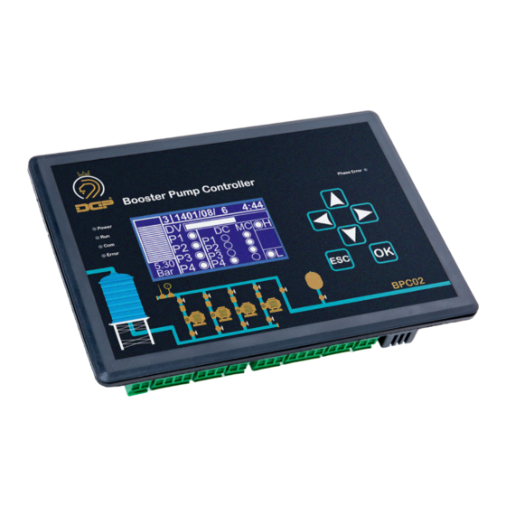
Menus Home Page On the home page, the controller displays the measured parameters to visualize the controller’s workflow. Different sections of the home page are depicted in the figure. Controller Mode 1: 1. Displaying the pressure graphically 2. Operating mode of the controller 3. -
Page 10: Introduction To The Functionality Of Direction Keys
Introduction to the Functionality of Direction Keys: Right Key: Function Description: By pressing the right key on the main screen, the values measuremed by the phase controller are displayed. In this screen, the main power frequency is shown with precision to 0.1. The first column corresponds to the voltages of each phase with neutral, and the second column corresponds to the voltage imbalance between each phase. -
Page 11: Up Key
Please note that in the Manual Settings page, the controller will exit the automatic control mode. After exiting this page, it will return to automatic mode, and all protections will remain active. Up Button: To access the Setpoint menu, press the Up button. Once inside the Setpoint page, we can adjust the Setpoint value by pressing the OK button and using the directional buttons (Up or Down). -
Page 12: Main Menu - System -System
2. Change Password: By selecting this option, we will enter a new page where we need to enter the old password in the first row and the new password in the next two rows. For example, to change the sys- tem password, we should follow these steps: Current Pass: 1111 New Pass: 2222... -
Page 13: Main Menu - System- Time Date
Main Menu – Time/Date: By selecting the third option from the menu, “Time/Date,” we can configure the time and date. In the “Time” section, we can set the time, and in the “Date” section, we can set the date. Main Menu – Hardware: The fourth option in the main menu is the “Hardware”... -
Page 14: Main Menu - System-Hardware-Floater
Main Menu – Page 1 - Floater - Hardware: The second option in the Hardware menu is “Floater,” which is used for controlling water level. 1. Type: We have three options for controlling water level: - Disable: If we don’t need water level control, we can disable this feature on the controller. -
Page 15: Main Menu - System -Hardware- Control
Main Menu – Page 1-2 - Control - Hardware: On the first page, in the “Pump” section, we can set the number of pumps. The controller supports up to 4 pumps in modes 2 and 3, which are changeover modes. In mode 1, we can use up to 6 pumps, with the first two being drivable and the remaining four being directly operated. -
Page 16: Main Menu - System -Hardware- Control
Main Menu – Hardware- Control -Page 3-4: Page 3 - Status: On this page, we can remove the checkmark next to the desired pump to exclude it from the system. The controller continues its operation without considering that pump. To re-enable the pump, we should return to this page and check the pump again. -
Page 17: Main Menu - System -Hardware- Control
Main Menu – Hardware- Control -Page 6: Sleep frequency = Start frequency + 2Hz Page 6 – Sleep In the sixth page, we’ll find the Sleep menu where we configure the sleep frequency. To obtain the Sleep frequency, first, we need to determine the Start frequency. Assuming the system requires a pressure of 5 bars, close the collector output completely and increase the driver frequency until the pressure is reached. -
Page 18: Main Menu - System -Hardware- Control
Main Menu – Hardware- Control -Page 8: Page 8 - Change Over: In the main menu, Page 8 covers the “Change Over” settings. This option controls the pumps switching: 1. If the “Enable” option is selected, the pumps will switch with each on/off cycle. -
Page 19: Main Menu - System -Hardware- Control
Main Menu – Hardware- Control -Page 12: Page 12 - Auto Service: Using the Auto Service option, the controller, by default, checks the time the pumps are off. To prevent the pumps from seizing when they are off, the controller momentarily turns on the pump for a user-defined period. -
Page 20: Main Menu - System Page 9-10 -Mfx - Hardware
5. FL: To use external level control, you need to select the “External” option on the Floater page. Then, by going to the MFX page, place one of the multi-function inputs on “FL” and connect the control wire for external level control to the same input. -
Page 21: Main Menu - System Serial Number -Mfx - Hardware
Main Menu –– Hardware - Serial Number: You can define a serial number for the controller, and this serial number will be displayed at the top of the error pages.. Main Menu –– Hardware - Network: This page in 7th menu of the controller is used for configuring the RS485 network address. -
Page 22: Booster Pump Controller In Firefighting Project
Booster Pump Controller in Firefighting Projects To set up the DGP booster pump controller for firefighting projects, you need to hold down the OK button for 3 seconds to enter the settings. After entering the settings page, navigate to the Hardware section and select the fourth option, Control. -
Page 23: Controller Booster Pump Troubleshooting Table
Troubleshooting Table for the Booster Pump Controller Errors Fault Finding Pump 1,2,3,4 Error Bi-metal or thermal switch has operated. Check motor current and bi-metal. Check wiring according to the diagram at terminals PR1~PR4. Drive Error Drive has an error, check the error code on the drive LCD. Check wiring according to the diagram at terminals M2.3 Drive Fault, and drive fault relay. - Page 24 Attention! 1. Set the desired pressure in SetPoint. 2. In the manual section, check the speed of all pumps with the drive (DC1, DC2, DC3, DC4) at a low frequency of about 3Hz. 3. In the manual section, check the speed of all pumps by activating the contactors (MC1, MC2, MC3, MC4). 4.
-
Page 25: Modbus Controller Addresses
ModBus Controller Addresses: Porotocol ModBus-RTU Com Port Setting 9600 8-N-1 Bit Address Description Address Value Output 0 Status 0:OFF 1:ON Output Status 0:OFF 1:ON Output Status 0:OFF 1:ON Output 3 Status 0:OFF 1:ON Output 4 Status 0:OFF 1:ON Output 5 Status 0:OFF 1:ON Output 6 Status... - Page 26 Pump5 Status 0:OFF 1:ON Pump6 Status 0:OFF 1:ON Drive Fail 0:Normal 1:Failed 0:Normal Pump1 Fail 1:Failed Pump2 Fail 0:Normal 1:Failed Pump3 Fail 0:Normal 1:Failed 0:Normal Pump4 Fail 1:Failed Pump5 Fail 0:Normal 1:Failed 0:Normal Pump6 Fail 1:Failed 0: Not Co1111ected Floater L Level :Con11ected 0: Not Connected...
- Page 27 Pump Activation 4100 0:Disable 1:Enable 50 Pump 6 Activation 4101 0:Disable 1:Enable 51 Control Phase Activation 4106 O:Disable 1 :Enable Changging Activation 4107 O:Disable :Enable 53 Time Changging Activation 4108 0:Disable 1:Enable 54 Reserve Automatic Activation 4109 O:Disable :Enable 55 Reserve Automatic Type 4110 O:NO...
- Page 28 56 Control Status 4173 57 Sleep Gap 4175 1-100 0.01Bar Auto Service Offlime 4177 1-9999 Hour Auto Service On Time 417B 1-999 0.1Sec Auto Service Interval 4179 1-99 Disable 61 MFl1Type 41B0 MFl1 62 MFl2Type 4181 Refer to MFl1 63 MFl3Type 4182 Refer to MFl1...
-
Page 29: Wiring Diagram (2 Pumps 1 Drive - Mode 3)
Wiring Diagram (2 Pumps, 1 Drive – Mode 3) -
Page 31: Wiring Diagram (4 Pumps 1 Drive - Mode 3)
Wiring Diagram (4 Pumps, 1 Drive – Mode 3) -
Page 33: Wiring Diagram (1 Pump 1 Drive - Mode 1)
Wiring Diagram (1 Pumps, 1 Drive – Mode 1) -
Page 35: Wiring Diagram (2 Pumps 1 Drive - Mode 1)
Wiring Diagram (2 Pumps, 1 Drive – Mode 1) -
Page 37: Wiring Diagram (2 Pumps 2 Drives - Mode 1)
Wiring Diagram (2 Pumps, 2 Drive – Mode 1) - Page 39 NOTE...
- Page 40 NOTE...
- Page 41 NOTE...
- Page 42 021 - 77797006 dgpplc www.DGParsian.com...
Need help?
Do you have a question about the BPC-02 and is the answer not in the manual?
Questions and answers