Table of Contents
Advertisement
Quick Links
Assembly instructions
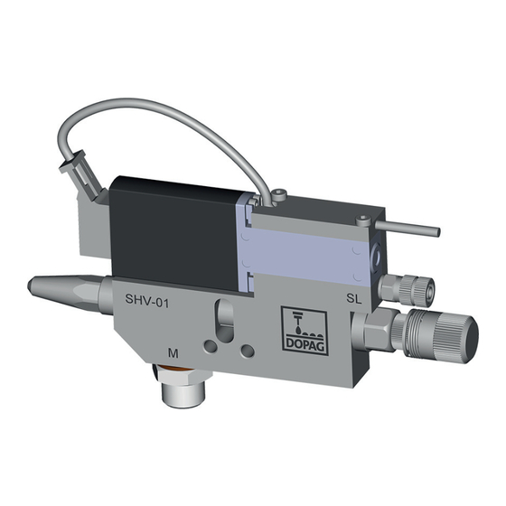
Shot valve (SHV-01)
© DOPAG AG • Langackerstrasse 25 • 6330 Cham • SWITZERLAND
Phone: +41 41 7855-757 • E-mail: info@dopag.ch • Web: www.dopag.com
Contents
General
Safety rules
Overview and function
Options
Assembly
Maintenance
DOPAG spare parts
Disposal
EC Declaration ofincorpo-
ration
8/2021
1
2
3
4
5
6
7
8
9
10
Advertisement
Table of Contents

Summary of Contents for HILGER u. KERN DOPAG SHV-01
- Page 1 Assembly instructions Shot valve (SHV-01) Contents General Safety rules Overview and function Options Assembly Maintenance DOPAG spare parts Disposal EC Declaration ofincorpo- ration © DOPAG AG • Langackerstrasse 25 • 6330 Cham • SWITZERLAND 8/2021 Phone: +41 41 7855-757 • E-mail: info@dopag.ch • Web: www.dopag.com...
- Page 2 SHV-01/0000000145-001-EN...
-
Page 3: Table Of Contents
Contents General..................5 Object of assembly instructions . - Page 4 Electrical connection............. . . 27 6.4.1 Connection assignment for solenoid valve.
-
Page 5: General
General General Object of assembly instructions These assembly instructions are to ensure the safe, intended and efficient use of the module. They contain the relevant information for safety, overview, function, assem- bly, maintenance and disposal. The required information can be located in the as- sembly instructions using the contents index, title and marginal columns. -
Page 6: Note On Changes
General Note on changes Text, illustrations and data are commensurate with the technical status of the ma- chine at the time of these operating instructions going to print. The company re- serves the right to make changes in the interests of ongoing development. Symbols and pictograms The operating instructions contain various symbols and pictograms. -
Page 7: Safety Advice
General Safety advice There are four types of safety information: Danger, warning, caution, note. They con- tain: Source of danger, consequences of the risk and avoidance measures to be tak- Danger Signal word to indicate a danger with a high risk that will lead directly to death or se- rious physical injury. -
Page 8: Mandatory Signs
General Mandatory signs Mandatory Mandatory signs prescribe specific courses of action. They must be followed, as they help protect against injury. Wear protective gloves Wearing protective gloves prevents contact with toxic substances. Caustic burns and poisoning are avoided. Wear protective goggles Parts of the equipment operate under pressure and spraying substances can cause damage to eyes. -
Page 9: Safety Rules
Safety rules Safety rules Intended use The DOPAG shot valve is partly completed machinery as defined in the directive 2006/42/EC. The products are solely intended to discharge viscous liquids such as greases and oils. The materials to be processed must be approved by DOPAG Ser- vice. -
Page 10: Product Safety
Safety rules Product safety The module conforms to acknowledged rules of engineering and technology and the relevant safety regulations. The correct operation of the module is required to avoid damage and accidents. Operating it incorrectly or subjecting it to abuse, or ignoring the application limits and the safety instructions, may imperil: •... -
Page 11: Hazardous Zones
Safety rules Hazardous zones The hazardous zone denotes the area on a module and/or in its vicinity in which there are dangers to safety or personal health. There are various danger zones around the module. All safety regulations given in the assembly instructions and in- formation signs on the module must be observed. -
Page 12: Warranty And Liability
Safety rules Warranty and liability Claims under the warranty and liability for personal and material damage are exclud- ed if they are due to one or several of the following causes: • Improper use of the module. • Improper assembly, commissioning, operation and maintenance. •... -
Page 13: Overview And Function
Overview and function Overview and function Basic function Shot valves of the SHV-01 series are extremely fast-switching valves. The valve be- longs to the family of the needle valves and is suited for processing materials which can be sprayed in continuous or shotwise operation. The valves are primarily used for the application of sealants, adhesives and oils. -
Page 14: Overview
Overview and function Functional diagram Overview In these assembly instructions, additional options are described which are possibly not contained in the module supplied to you. These assembly in- structions cover all possible versions and variants of this line of products. LV nozzle Basic body Needle... -
Page 15: Needle Variants
Overview and function DOPAG G 1/8" for Nozzle Nozzle ver- Nee- Remark item No. pressure sion sensor 1004396 Base body without needle for nozzle extensions 4.2.2 Needle variants Apart from the diameter, the needles differ only by the type of usage. DOPAG item No. -
Page 16: Technical Data
Overview and function Technical data 4.3.1 Dimensions Performance / Consump- tion / Weight Performance / Consumption Air consumption approx. 150 l/min. (at 3 bar, 1.0 mm noz- zle) Metering cycle up to 100 metering cycles / second Material pressure max. 100 bar Control air pressure min. -
Page 17: Compressed-Air Connection
Overview and function 4.3.2 Compressed-air connection The module must be connected to a compressed-air supply unit. Therefore, a Com- pressed-air connection (4.2 Overview) is fitted. The supply line must have an inside diameter corresponding to the technical data and supply a constant pressure of 6 bar. - Page 18 Overview and function 18/4 SHV-01/0000000145-001-EN...
-
Page 19: Options
Options Options In these assembly instructions, additional options are described which are possibly not contained in the assembly supplied to you. These assembly in- structions cover all possible versions and variants of this line of products. Nozzle extension kit (DV) The use of DV nozzles enables to tilt the devices towards each other without ex- tremely increasing the required installation area. -
Page 20: Stroke Detection
Options Stroke detection Raster needle with stroke detection Plug braun (1) 10 ... 30 VDC 100 mA max. Last schwarz (4) blau (3) The stroke must be open by at least 10 raster steps to ensure a trouble-free operation of the proximity switch. DOPAG Base body in- Raster nee-... -
Page 21: Pressure Sensor
Options Pressure sensor The measuring pressure causes an elastic deformation of the membrane. By sup- plying energy, this deformation is proportionally converted into an electrical signal that can be subsequently evaluated. Pressure sensor G1/8“ Spacer ring (only supplied with 1009568) Transmitter + Vcc OUT/GND... -
Page 22: Heating
Options Heating The heating is used to heat the components. This facilitates processing of specific materials. Heating cartridge and temperature sensor must be electrically connected. A clamping screw is provided in order to link the heating case with the equipotential bonding. -
Page 23: Sensor Scanning At Light Barrier
Options Sensor scanning at light barrier By using the light barrier, metering and idle times < 5 msec can be selected. As soon as material crosses the light barrier, it is detected that material has been metered. The evaluation unit can be taken up by a top-hat rail TS 35 x 75.5 or 15. DOPAG item No. - Page 24 Options Sensor scanning compo- nents SHV-01 Evaluation unit Top-hat rail Light barrier holder Plug-in connection Fiber-optic light barrier Connecting cable Evaluation unit Display Locking lever for optical fi- Dust cover / Sensor cover M8 connector (FS-N41C) Mark for optical fiber Optical-fiber connection 24/5 SHV-01/0000000145-001-EN...
-
Page 25: Silencer Kit
Options Functional diagram Silencer kit For noise level reduction, the silencer kit can be installed on the shot valve. Kit con- tents: 2 silencers + 2 elbows The increased switching frequency (max. 200 Hz) of the shot valve may cause discomfort if you are working in its vicinity for prolonged periods without be- ing protected. - Page 26 Options 26/5 SHV-01/0000000145-001-EN...
-
Page 27: Assembly
Assembly Assembly Transportation The module is packaged and delivered by the manufacturer in a proper manner. It is protected for transport and against weather conditions, and provided with suitable packaging materials. Transport the module to the application site in packaged condition if possible and only remove package before first use. -
Page 28: Compressed-Air And Material Connection
Assembly 6.4.3 Compressed-air and material connection Material outlet Solenoid valve Material inlet 1/4" Control air to M5 connec- tion DANGER Danger of bursting when using unauthorized hoses! The use of unauthorized hoses which do not withstand the maximum working pres- sure of the pressure line may have serious consequences for life and limb! ►... -
Page 29: Installation In A System
Assembly Installation in a system The valves can be installed in any position. The distance to the application surface depends on the desired application width. Shotwise operation of the valve causes natural vibrations. Therefore, make sure that the valve is tightly and firmly installed. Excessive natural vibrations of the machine to the valve must be prevented. -
Page 30: Commissioning Of Evaluation Unit
Assembly WARNING Risk of nozzle splashing! During operation, the material gushes out of the nozzle under high pressure! ► Do not bring any parts of your body into the immediate vicinity of the point of dis- charge. The valve must not be pointed towards persons. Wear eye protection and protective clothing. -
Page 31: Discharge
Assembly Changeover of the output Changeover of output logic "NC contact/NO contact" logic Press to go to "L-ON / D-ON" and wait. to go to "Dark ON". Confirm the entry with Press 3 times. Saturation adjustment To ensure optimum operation of the device, the saturation should be adjusted as follows: simultaneously. - Page 32 Assembly Control knob without nee- dle detection Adjustment using Allen wrench Improper handling could cause damage to the nozzle and the nozzle needle. Reduce the material discharge (by turning the adjusting screw clockwise) only when material is discharged. After closing the nozzle, do not rotate the adjusting screw clockwise any further! In case of long downtimes, material can remain in the valve if it is under pres- sure and has no connection to the outer air.
-
Page 33: Maintenance
Maintenance Maintenance General Maintenance work must be undertaken by properly trained maintenance staff (2.3 Target audience). WARNING Danger arising from maintenance work! If you undertake maintenance work without having received the necessary training, system safety is no longer guaranteed. This can cause serious physical injury or death. - Page 34 Maintenance Sealing liquid For filling the seal chambers, DOPAG recommends Mesamoll sealing liquid. For sil- icone applications, we recommend silicone oil. SL designation Container DOPAG article no. Mesamoll 1 liters (plastics) 26.05.010 Mesamoll 5 liters (plastics) 26.05.011 Silicone oil 50ml (plastics) 26.05.009 Greases The greases used for maintenance are shown in the enclosed parts lists with their...
-
Page 35: Maintenance Of The Modules
Maintenance SL designation Product DOPAG article no. GL08 Loctite 326, Activator 7649 53.09.006 / 53.09.012 GL09 Anti seize paste 1003012 GL10 GL11 Araldit AW 106 MPHärter HV A: 53.09.015 B: 53.09.016 953 U MP GL12 GL13 Loctite Epoxy Adhesive 22035683 GL14 Loctite 270 1005330... -
Page 36: Nozzle
Maintenance DANGER Danger of explosion when using solvents! When using solvents based on halogenated hydrocarbons, such as trichloroethane, chemical reactions can be caused on aluminum and on galvanized parts. The parts can oxidize and be destroyed as a result. In extreme cases, the reaction can occur in an explosive manner. -
Page 37: Dopag Spare Parts
DOPAG spare parts DOPAG spare parts WARNING It is dangerous to use incorrect spare parts! Using spare parts that have not been tested and approved by DOPAG means that system safety is not guaranteed. This can cause serious physical injury or death. ►... - Page 38 DOPAG spare parts 38/8 SHV-01/0000000145-001-EN...
-
Page 39: Disposal
Disposal Disposal Check the reusability of materials and system parts prior to disposing of them. Re- cycle them as far as possible. Careless or incorrect disposal can result in unforeseen consequences. Materials and system parts should be disposed of in a manner that is proven to be harmless to humans, nature and the environment. - Page 40 Disposal 40/9 SHV-01/0000000145-001-EN...
-
Page 41: Ec Declaration Of Incorporation (As Per Directive 2006/42/Ec)
EC Declaration of incorporation (as per directive 2006/42/EC) EC Declaration of incorporation (as per directive 2006/42/ We, the manufacturers of the partly completed machinery, declare that the following machine is in conformity with the directives listed below and that the mentioned stan- dards were referred to. - Page 42 EC Declaration of incorporation (as per directive 2006/42/EC) 42/10 SHV-01/0000000145-001-EN...
- Page 43 EC Declaration of incorporation (as per directive 2006/42/EC) SHV-01/0000000145-001-EN 10/43...
- Page 44 DOPAG Dosiertechnik und Pneumatik AG Langackerstrasse 25 6330 Cham | Switzerland 44/10 SHV-01/0000000145-001-EN...
Need help?
Do you have a question about the DOPAG SHV-01 and is the answer not in the manual?
Questions and answers