
Related Manuals for SOLATHERM PV360R

Summary of Contents for SOLATHERM PV360R
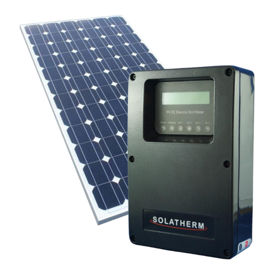
- Page 1 Power Control Equipment Model: PV360R Heating with Secondary Output Power Control Equipment (PCE) PV DC Electric Hot Water Owner Manual 1/52 Barnett Ave, Glynde SA 5070 Phone (08) 8337 8881 www.solatherm.com.au...
- Page 2 WARNING The controller is only to be connected to a hot water cylinder specifically designed and configured for use with the Solatherm DC controller (P.C.E.). It is not for retrofit. WARNING If the equipment is used in a manner not specified by the manufacturer, the protection provided by the equipment may be impaired.
- Page 3 All electrical connections must be terminated before switching any component on. The power to the Solatherm solar control unit and water heater must NOT be switched on until the water heater is completely filled with water and all air bled from the system.
-
Page 4: Symbol Glossary
WATER CONNECTIONS FOR STORAGE VESSEL Please ensure all plumbing installation work is carried out in accordance with AS3500 and that a non-return valve is installed in the incoming water line. Maximum inlet pressure 700kPa, minimum inlet pressure 350 kPa. A pressure relief valve must be fitted in accordance with AS 3500, rating 850kPa 10kW. -
Page 5: Table Of Contents
Shut down Procedure........................... 20 Warranty ................................ 21 Warranty Definitions ..........................21 Warranty Conditions ..........................21 Warranty Exclusions ..........................22 Commissioning .............................. 23 System Information - Form A ........................23 System Diagram ............................. 25 Technical Data ............................... 25 PV360R-Draft V5 P a g e... -
Page 6: About
When the temperature is reached the unit will turn the element off until the water temperature falls. Once the water is up to temperature, Solatherm units with diversion are able to divert surplus power for another purpose such as battery storage. The controller monitors the temperature of the stored water to ensure maximum hot water is maintained. -
Page 7: Display
Display Figure 1. Solatherm Control Units are independent from the grid and require no mains power connection to operate, hence, the unit will only operate and display user information when there is sufficient energy from the sun. It is normal for the LCD display and lights to flicker or not fully display in low light conditions. -
Page 8: Basic System Configuration
Basic System Configuration Figure 2. P a g e... -
Page 9: Start-Up Procedure
Start-up Procedure NOTE: ENSURE HOT WATER VESSEL IS COMPLETELY FILLED WITH WATER BEFORE COMENCING START UP PROCEDURE. 1. Turn on Isolator. RED LED POWER LIGHT SHOULD BE ON. The LCD will illuminate and start to indicate incoming power (providing supply voltage is over 120 Volts). -
Page 10: Frequently Asked Questions
Q: The controller LCD and lights are flashing or resetting in the morning, during the day or at the end of the day? A: The Solatherm control unit is powered by the photovoltaic array. There is no connection to mains/grid power required for standard operation. The controller will only operate when sufficient energy is available from the sun. - Page 11 Q: Run out of hot water or warm water only. 1. The hot water produced has been consumed during the day. 2. Not enough solar input during the day. Ensure booster is connected and the AC boost timer settings are correct for the household demand or season. Q: I can see the second output is active but I have no hot water? 1.
-
Page 12: Troubleshooting
Troubleshooting All observations for potential faults need to be conducted in clear daylight conditions. Observation Fault Should this occur in bright sunshine please contact your installer. No Fault if seen in low Dim/flickering LCD display light conditions. Re-check in brighter &... -
Page 13: Installation Instructions
Installation Instructions Wiring Diagram - Controller WARNING INCORRECT POLARITY WILL DAMAGE THE CONTROLLER NO WARRANTY FOR POLARITY DAMAGE 25 AMP 600V HRC Figure 3. 12 | P a g e... -
Page 14: Cylinder Mounted Pce Controller
On the Ground Cylinder mounted PCE controller Choose a suitable location, giving consideration to the following: 1. Vertical position of cylinder and controller consideration to cable length and PV main array isolator location and diversion requirements. 2. It is important to mount the controller out of the direct sunlight as it will make visual reading of the LCD display difficult. -
Page 15: Connection: Controller To Storage Water Vessel
Connection: Controller to Storage Water Vessel 1. The lower DC connection is factory wired. 3. Remove lower DC element cover if adjustment of the thermostat is required. The thermostat is factory set to 65 degrees. 4. Ensure Lower Thermostat which is spring located onto vessel surface has not been disturbed during installation and is sitting in place and secure. -
Page 16: Connection - Main Array Input
Connection - Main Array Input 1. An isolating switch in accordance with clause 4.8.2.3 AS/NZS 3000:2018 shall be installed for the water heater. 2. Connect a cable from the Isolator into connector box. Ensure Polarity on the connections is correct. TEST the polarity at the test point located on the connection board BEFORE INSTALLTION OF THE 25AMP (600V) HRC FUSE. -
Page 17: Connection - Secondary Output
Connection - Secondary Output 1. Suitable cable cab be connected to the secondary output in the connection box to connect with a secondary DC device such as an inverter. 2. On the connection board, note the positive and negative output connection on the lower RH connector block 3. -
Page 18: Connection - Boost Element - Ac
Connection - Boost Element - AC The 240V A/C Booster supply cable must be installed in accordance to Australian Standard AS3000 and by a qualified person. Note: Never energise the element until the water vessel is filled and bled! 1. Remove top booster 240V A/C element cover. 2. -
Page 19: On The Roof
ON THE ROOF The main array must be installed to Australian standards and all relevant local authority requirements by an authorised installer. Consideration must given to the position of the isolator in relation to the final controller position. The main array must be earthed with the earth cable into the isolator. -
Page 20: Commissioning Start Up
8. Turn on 240V AC booster isolator and breaker switch in household fuse box. 9. Test and record data on the Commissioning sheet in this booklet and make a copy for submission to Solatherm. Form A 19 | P a g e... -
Page 21: Shut Down Procedure
Shut down Procedure 1. Turn off main array Isolator (lock switch if required) 2. Controller should now have no information displayed and is OFF. 3. Turn off 240V AC Booster Isolator and breaker switch in household fuse box. 20 | P a g e... -
Page 22: Warranty
3. The option to replace or repair a failed component is at the sole discretion of Solatherm. 4. Where any part is repaired or replaced the duration of the original warranty period is still applicable. -
Page 23: Warranty Exclusions
7. The system installed must be sized in accordance with manufacturers guidelines. 8. Any repair under warranty must be approved by Solatherm prior to the repair or all costs are bore by the person who contracted the repair. Warranty Exclusions The following exclusions may cause the Solatherm warranty period to become invalid and/or may incur a service charge and/or cost of parts used during repairs. -
Page 24: Commissioning
Commissioning System Information - Form A Owner’s Name Installation Address Suburb State Post Code Telephone System Purchased from Installer’s Name Installation Date Contact Number CEC Number Job Number Type of Installation Replacement Unit Type Replaced DC PV Hot Water Controller Controller Model Serial Number All Output Connections terminated... - Page 25 Is the array installed as per installation advise form? (Form 2) If not describe why? Installer I hereby certify that this system has been installed according to all relevant Certification regulatory and statutory requirements and in accordance with Solatherm Installation Instructions. COC Accreditation Name Number...
-
Page 26: System Diagram
System Diagram This diagram must be fully completed and retained with all COC's for service personnel. Secondary Output To: Model ....Date Created ../../..Array Size # Panels Capacity # Strings .....L DC Cable Size DC Isolator Is Array Earthed? Signed ...... -
Page 27: Technical Data
Technical Data PV String Input Data Max. DC Input Power 10 kW Array Strings 1 or 2 Max. DC Input Voltage 600 VDC String Configuration Single or Parallel Max. Input Current 25.0 A Input Reverse Polarity Protection Max. Output 10 kW Max.
Need help?
Do you have a question about the PV360R and is the answer not in the manual?
Questions and answers