Table of Contents
Advertisement
Quick Links
Advertisement
Table of Contents
Troubleshooting

Summary of Contents for Hien WLRK BM/B3 Series
- Page 1 Installation and Operation Manual Triple Heating Pump Unit (WLRK- BM/B3 Series)
- Page 2 Dear Users, Thank you for selecting air source heating pump unit! ◇ To ensure the safe use of this product, please read this Manual carefully before installation and operation, and keep it properly for reference when necessary. ◇ Be sure to install the earth leakage protection device. ◇...
- Page 3 1. SAFETY INSTRUCTION This unit uses a flammable refrigerant. If refrigerant leaks and comes in contact with fire or heating part, it will create harmful gas and there is risk of fire. Read the USER MANUAL carefully before operation. Further information is available in the USER MANUAL, SERVICE MANUAL, and the like Service personnel are required to carefully read the USER MANUAL and SERVICE MANUAL before operation.
- Page 4 If the supply cord is damaged, it must be replaced by the manufacturer, its service agent or similarly qualified person in order to avoid a hazard. The appliance shall be installed in accordance with national wiring regulations. The machine is designed A-weighted sound pressure level below 70 dB.
- Page 5 · That capacitors are discharged: this shall be done in a safe manner to avoid possibility of sparking; · That there no live electrical components and wiring are exposed while charging, recovering or purging the system; · That there is continuity of earth bonding. Link to the Manual www.hien-ne.com...
-
Page 6: Table Of Contents
Contents Chapter 1 Identification Symbols and Meanings ................. 1 Chapter 2 Instructions on the Safety of Specific Installation Personnel ..........2 Chapter 3 Dimensional Drawings of the Equipment ................6 Chapter 4 Unpacking and Details of Accompanying Accessory Kit ........... 8 Chapter 5 Requirements for Equipment Installation ................ -
Page 7: Chapter 1 Identification Symbols And Meanings
Chapter 1 Identification Symbols and Meanings 1. Warning symbols and meanings Fire warning Indicating that there are flammable materials and attention shall be paid to fire prevention. Electric shock warning Indicating that the object is electrically charged, and touching it may cause an electric shock. -
Page 8: Chapter 2 Instructions On The Safety Of Specific Installation Personnel
Recycling symbol. Please send it back for recycling. Watch out for danger. Indicating a situation that may cause damage to equipment or property. Chapter 2 Instructions on the Safety of Specific Installation Personnel Always comply with the following instructions and regulations on safety. Regulations on installation sites Warning: ... - Page 9 Warning: As a combustible substance, it shall be kept away from open fire. Be careful with fire; Do not pierce through or burn the components for refrigerant circulation; The equipment shall be stored in a well-ventilated room without a continuously operating ignition source to prevent mechanical damage (e.g.
- Page 10 Do not leave the unit unattended after removing the service cover. Warning: Before installing the equipment, please read carefully the circuit diagram of the equipment (attached to the inside of the terminal box on the right side of the equipment).
- Page 11 Installation and commissioning of the unit Warning: Do not leave the unit unattended after removing the service cover; Do not touch the blade when the equipment is energized, for the fan may start suddenly; Do not stay at the air inlet or the aluminum fin of the equipment when it is in operation, so as to avoid personal injury;...
-
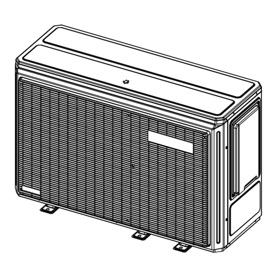
Page 12: Chapter 3 Dimensional Drawings Of The Equipment
Chapter 3 Dimensional Drawings of the Equipment Equipment Model: WLRK-6 (8/10) I BM/B3 Page 6... - Page 13 Equipment Model: WLRK-12 (14) I BM/B3, WLRK-12 (14) II BM/B3 Page 7...
-
Page 14: Chapter 4 Unpacking And Details Of Accompanying Accessory Kit
Chapter 4 Unpacking and Details of Accompanying Accessory Kit ② ① ③ ④ Page 8... - Page 15 Name of Accessory Quantity Installation and Operation Manual (including the certificate of conformity and the packing list) Shock-absorbing rubber block Y-shaped filter Display communication line Temperature sensor Display Page 9...
-
Page 16: Chapter 5 Requirements For Equipment Installation
Chapter 5 Requirements for Equipment Installation 5.1 Equipment installation site Warning: Main unit The equipment shall be stored in a place where there are no ignition sources (e.g. open fire, gas appliances in operation, or electric heaters in operation); ... - Page 17 Caution: Do not pile the units one above another; Do not hang the unit from the ceiling. Page 11...
- Page 18 Installation Mode A (mm) B (mm) C (mm) D (mm) E (mm) F (mm) Single-unit installation ≥2000 ≥500 ≥500 ≥500 ≥1000 Double-unit installation ≥2000 ≥500 ≥500 ≥500 ≥1000 ≥1000 Page 12...
-
Page 19: Requirements For Equipment Installation
5.2 Requirements for equipment installation A strong wind (≥18 km/h) blows into the air outlet of the outdoor unit, resulting in a short circuit (exhaust gas is inhaled). This may lead to the following results: The performance of the unit will be degraded; ... - Page 20 A place with acidic or alkaline vapors. When the unit is to be installed by the seaside, make sure that the outdoor unit is not directly exposed to sea winds, lest it should be corroded by the air with high salinity and its service life should be shortened.
- Page 21 Warning: In any case, the following principles shall be abided by: The equipment shall be installed on a base that is at least 150 mm tall; Before installation, inspect the base with a level instrument to ensure the levelness of the equipment;...
-
Page 22: Requirements For Equipment Hoisting
M10 nut M10 spring washer M10 flat washer Main unit Shock-absorbing rubber block M10 expansion bolt Base 5.3 Requirements for equipment hoisting Warning: To avoid dangers, contact the personnel with relevant qualification certificates and ask them to hoist the equipment. ... -
Page 23: Requirements For Water Supply And Drainage
√ × The equipment deforms due to extrusion. ② Fix the equipment to the structural frame for installation: Warning: After placing the equipment on the structural frame for installation, fix it with bolts immediately and then remove the slings. Do not leave it unattended, lest an accident should occur. -
Page 24: Removal And Installation Of The Front Panel Of The Equipment
5.5 Removal and installation of the front panel of the equipment Warning: To avoid injury, do not touch the air inlet or the aluminum fin of the equipment when it is in operation. Warning: Do not do any work when the equipment is energized. All the work must comply with applicable local laws and regulations. -
Page 25: Chapter 6 Installation Of The Engineering Pipes
Chapter 6 Installation of the Engineering Pipes 6.1 Requirements for the pipes Caution: All the work must be done by the personnel with relevant qualification certificates; Do not apply excessive force when connecting the on-site pipes and make sure that the pipes are aligned properly;... - Page 26 Caution: Inject water to get a water pressure of approximately 2.0 bar. Use the air exhaust valve to remove as much air as possible from the water circuit. The air in the water circuit may cause an equipment failure; ...
-
Page 27: Use Of Ethylene Glycol For Freeze Protection
6.2 Use of ethylene glycol for freeze protection Frosting can cause damage to the system. To prevent the hydraulic components from freezing, the system has special anti-freeze functions such as water pipe freeze protection and drainage, including starting the pumps at a low temperature. However, in case of a power failure, these functions cannot provide the system with sufficient protection. - Page 28 ② Concentration of the ethylene glycol required The concentration of the ethylene glycol required depends on the expected minimum outdoor temperature and whether you want to protect the system from bursting or freezing. To prevent the system from freezing, you need more ethylene glycol. Add ethylene glycol according to the table below.
-
Page 29: Application Scenario Graph
6.3 Application scenario graph (the application example given below is for reference only) Page 23... -
Page 30: Instructions On The Installation Of Three-Way Magnet Valves
Caution: Please be sure to install one-way valves at the water outlets of the external heat sources and the heating pumps, lest short circuit of the water circuit should occur to result in self-circulation between the external heat sources and the heating pumps and a poor user experience;... - Page 31 When three-way magnet valve 1 OFF is turned on, three-way magnet valve magnet 1 will be switched over to the direction ①=>②, and the heating pump is connected to the hot water tank, so as to heat the latter; ...
- Page 32 If Zone B needs heating, three-way magnet valve 3 OFF is turned on, and three-way magnet valve 3 is switched over to the direction ⑦=>⑨, the buffer tank is connected to the floor heating to heat Zone B; If Zone B does not need heating, three-way magnet valve 3 ON is turned on, and three-way magnet valve 3 is switched over to the direction ⑧=>⑨, the buffer tank is disconnected from the floor heating, and the floor heating achieves self-circulation.
-
Page 33: Chapter 7 Electrical Installation
Chapter 7 Electrical Installation Warning: Electric shock hazard All wires must be connected by authorized electricians with relevant qualification certificates, and must comply with the applicable local laws and regulations; All cables and electrical components must comply with the local laws and regulations. -
Page 34: Schematic Wiring Diagram Of The Equipment's Main Power Supply
7.1 Schematic wiring diagram of the equipment’s main power supply: Engineering Strong Current Harness Engineering Weak Current Harness Main Cable Schematic Wiring Diagram of Single-phase Power Schematic Wiring Diagram of Three-phase Power a: Field Cabling b: Main Cable of Equipment c: Earth Leakage Circuit Breaker d: Overload Fuse Page 28... -
Page 35: Schematic Wiring Diagram Of The Equipment's Engineering Strong Current System
7.2 Schematic wiring diagram of the equipment’s engineering strong current system: Caution: The wiring of this zone is only for AC contactor action signals. Do not connect any electrical equipment with an electrical power greater than 300W directly to the equipment, lest the equipment should be damaged due to overload!!! ... -
Page 36: Schematic Wiring Diagram Of The Equipment's Engineering Weak Current System
7.3 Schematic wiring diagram of the equipment’s engineering weak current system: · The temperature sensing probes required by the system can be found in the terminal box on the right side of the equipment, and they shall be connected to the temperature sensors in the accessory package, as shown in the figure above. -
Page 37: Electrical Wiring Diagram
7.4 Electrical wiring diagram Equipment Model: WLRK-6(8/10) I BM/B3 Page 31... - Page 38 Equipment Model: WLRK-12(14) I BM/B3 Page 32...
- Page 39 Equipment Model: WLRK-12(14) II BM/B3 Page 33...
-
Page 40: Chapter 8 Instructions On The Display's Operation
Chapter 8 Instructions on the Display’s Operation 8.1 Description of the icons on the display wifi module is available but not connected to the Internet wifi module is available and connected to the Internet successfully, but not connected to the cloud Already connected to the cloud Displayed if there Off-peak power consumption status... - Page 41 Used to page down or adjust the parameter value [Down] Used to enter the setting menu or confirm [Set/Confirm] Used to set the mode [Mode] The main interface varies with the application scenario. The possible scenarios are described below: Main interface 1 (Single-Zone Water Main interface 2 (Single-Zone Room Temperature + Hot): Temperature + Hot Water):...
-
Page 42: List Of Menus
8.2 List of menus Curt. err Status query Query menu Version query Language Electricity metering Display bright gauge Screen lock Display setting Screen lock time Time and date Time of screensaver Daily Schedule Weekly Schedule Timed on/off Timer Cancel timer Sterilization Timer Silent Timer WIFI setting... -
Page 43: Basic Usage
8.3 Basic usage 8.3.1 Screen unlock If the “screen lock” icon appears on the screen, the display will not operate; press and hold button for three seconds, the display is operable, as shown in the figures below: Enabled/disabled setting of the lock screen function: to enter the setting menu interface, find “Display setting”... - Page 44 First, make sure that the [Hot water function] is set to “Enabled”; otherwise, it is impossible to switch on the hot water. On the main interface, click button to select the hot water zone, and then press button and click to confirm the switch-on/off of hot water production, as shown in the figures below: 8.3.3 Temperature adjustment On the main interface, click...
-
Page 45: Query Menu
8.3.5 Operation of time setting All time modifications (e.g. year, month, day, hour, minute, second) on the display are made in the same way; here, the modification of the year in the “Time and date” is taken as an example. Enter the “Time and date”... -
Page 46: Setting Menu
8.4.2 Status query interface When you need to view the current information about the unit (e.g. temperature, electrical components enabled, etc.), you may enter the status query interface for viewing. Click to switch over to view the output querying status information (if the circle on the right side of a component is green, it indicates that there is an output from the component), and click again to return to the analog querying status information. - Page 47 Please refer to 8.3.5 “Operation of Time Setting” for time modification. 8.5.3 Timer setting 8.5.3.1 Timed on/off Daily timed on/off to enter the setting menu and select “Timer”. On the main interface, click to enter the timer menu, select “Timed On/off” and click Click to enter the timed on/off menu, select “Daily Schedule”...
- Page 48 The unit is controlled as shown in the figure below. Hot Water Heating Cooling Cooling Hot Water 1:00 6:00 7:00 9:00 11:00 13:00 16:00 19:00 20:00 22:00 The operations of the unit are described as follows: Time Operation of Unit Prompt: If the start time is the same as the end time, the start time is 1:00 Switch-on in hot water mode...
- Page 49 Timer cancellation If you want to cancel all timed on/off settings by one operation (without affecting the setting of other timer functions), just follow the instructions as set forth in this section. Select “Cancel timer” in the “Timed on/off” menu, and click , and the confirmation window will pop up.
- Page 50 If the box is not checked, click to check and validate it. If the box is checked, click to cancel the checking, and it will not become valid on the day. According to the settings as shown in the figure below, sterilization will start at 21:00 on Monday and Wednesday.
- Page 51 to move to “Silent level”, and click Click to switch over the silent level (Level 1 and level 2) There are two groups of timer settings in total. Click to move to the circle, and click to use or cancel this group of timer settings (the circle of the timer used will be checked) Note: For time setting, refer to 8.3.5 “Operation of Time Setting”...
- Page 52 If the WIFI status shows “connected to cloud server”, the network has been configured for the display, and the display can be operated with the account in which the network configuration is completed. If the WIFI status displays other content or it is necessary to cancel the network configuration completed previously, operation can be carried out by the following steps (note: the unit cannot be operated with the account in which the network configuration is completed and the communication is achieved).
- Page 53 See the “Lower limit of cooling temperature rising” and “Upper limit of cooling Set temperature of min…max º C temperature rising” for set cooling range of min and max for details See the “Lower limit of heating temperature rising” and “Upper limit of heating Set temperature of min…max º...
- Page 54 Low temperature curve 3 Low temperature curve 4 Low temperature curve 5 Low temperature curve 6 Low temperature curve 7 Low temperature curve 8 High temperature curve 1 High temperature curve 2 High temperature curve 3 High temperature curve 4 High temperature curve 5 High temperature curve 6 High temperature curve 7...
- Page 55 output temperature 1 Curve 9 cooling 5…25 º C output temperature 2 Curve 9 heating ambient temperature -25…35 º C Curve 9 heating ambient temperature -25…35 º C Curve 9 heating 25…65 º C output temperature 1 Curve 9 heating 25…65 º...
- Page 56 Only when the module is running, and the water temperature and fin temperature meet the requirements, is it possible to enter the defrosting successfully by clicking . At this moment, the current state of the module will be switched over to defrosting; otherwise, the original state will be maintained. 8.5.7 History error query All the errors (including the errors for which resetting has been completed) will be recorded in the controller.
- Page 57 on the “Floor dry up” option to have the If the floor dry-up function has been turned on, click confirmation window pop up to close this function (as shown in the figure below). Click to confirm that the floor dry-up function is turned off, and the pop-up window is closed, or click to cancel your choice and close the pop-up window.
- Page 58 Click to have the confirmation window pop up. Click to confirm that the force hot water mode is turned on, and the pop-up window is closed, or click to cancel your choice and close the pop-up window. on the “Force hot water” option to If the forced open hot water function has been turned on, click have the confirmation window pop up to turn off this function.
- Page 59 The holiday away mode is often used to prevent the water circuit from freezing while you are going out on holiday in winter. This mode starts after you leave and ends before you come back. to find “Holi. Mode Set”; click On the main interface, click to enter the setting menu, click to find “Holiday Away”;...
- Page 60 to select “Function Use”, and click to set to “Use” (click again to set to “No Use”), Click and the holiday home function is turned on. The setting of “START” and “END” shall be operated by reference to 5.3.5 “Operation of time setting”.
-
Page 61: Setting Of The Multi-Zone Mode
If you do not click “Logout,” you can enter the advanced setting interface next time without the need to enter the password (unless the equipment is re-powered on or no operation is carried out for a long time). If you want to enter “Advanced setting”, you need to enter the password. 8.5.14 Smart grid When entering “Advanced setting”, enter a password with the high-level permission to obtain the permission to set the smart grid function. -
Page 62: Chapter 9 Instructions On Other External Heat Sources
8.6.3 Single-zone room temperature + hot water: The system includes single-zone air conditioning room temperature control and domestic hot water control. If air conditioning needs to be controlled by the room temperature, click in “Main interface” > “Setting menu” > “Advanced setting” > “Parameter setting”... - Page 63 SW1.1 SW1.2 No auxiliary electric heater output IBH1 auxiliary electric heater output IBH2 auxiliary electric heater output IBH1+IBH2 auxiliary electric heater output Note: OFF on SW terminal indicates “0”, and ON indicates “1”. IBH2 auxiliary electric heater output is located in the lower middle part of the main board as shown in the figure above. Before using the auxiliary electric heater, connect the temperature sensor in the accessories to “Total Water Outlet Temperature”...
-
Page 64: Chapter 10 Operation Instructions On Connection
If the external heat source needs to be added to the system, connect it behind the heating pump in parallel (If an auxiliary electric heater is provided, connect the external heat source behind the auxiliary electric heater). To use the external heat source, you need to set the parameters. Set “External heat source” to “Enabled” in “Advanced setting →... -
Page 65: Chapter 11 Trial Operation
Chapter 11 Trial operation Warning: Check whether the appearance of the unit and the pipeline system in the unit are damaged during transportation; Check whether the fan blades are working well; Check whether the system pipeline, water supply pipes, return water pipes, pressure gauges, valves, and other equipment are installed correctly;... -
Page 66: Chapter 12 Common Faults And Troubleshooting
Chapter 12 Common Faults and Troubleshooting Fault Reset Mode Alarm Action Troubleshooting Faults with the controller itself An alarm goes off, and the 1. Initialize all parameters. Switch-on EEPROM data error equipment cannot be 2. If the fault is still not fixed after initialization, reset started. - Page 67 1. Check whether the water flow is too small: Clean the filter and check whether the water flow switch is abnormal. Overload of the An alarm only, and no 2. Check whether the feedback signal line is auxiliary electric shutdown short-circuited or open- circuited: Reconnect the heater wires correctly.
- Page 68 1. Check whether the water temperature goes beyond the design range: Adjust the set temperature of the unit. 2. The water temperature or exhaust temperature Shut down the compressor probe line is short-circuited or open- circuited: Too high exhaust “Non-frequency-decrease Reconnect it correctly.
- Page 69 damaged (if damaged, replace them). 3. Check whether the fan is faulty: Replace it. 1. Check whether the suction temperature and the exhaust temperature probes are faulty: Replace them. Abnormal difference 2. Check whether the suction temperature and the Shut down the compressor between the suction exhaust temperature probes are connected “Non-frequency-decrease...
- Page 70 Fault with J6 pressure sensor Fault with the hot Shut down the compressor water tank temperature Fault with the total water outlet Shut down the compressor temperature Fault with the total water outlet Shut down the external heat temperature of the source (AHS) system Fault with the water...
-
Page 71: Chapter 13 Leakage Fault And Troubleshooting
Limited faults: See the fault list. 3) Automatic resetting A The alarm can be reset automatically after the fault is fixed; The number of automatic re-settings is not limited; 4) Manual resetting M The alarm can be reset manually only on the controller after the fault is fixed; ... -
Page 72: Chapter 14 Maintenance And Servicing
2) Arrange for professional personnel to maintain the equipment on schedule. Chapter 14 Maintenance and Servicing The air source heating pump unit is a kind of equipment with a high degree of automation, and its status shall be inspected regularly. Its operational reliability and service life will be improved by long-term and effective maintenance and servicing. - Page 73 Warning: Do not dismantle the equipment for maintenance without authorization. Go to the after-sales service station as designated for maintenance; Make sure that technicians have the relevant qualification certificates and have been authorized and that they perform maintenance and repairs under the supervision of the personnel qualified for using flammable and explosive refrigerants;...
- Page 74 cooling system, stabilize it for 5 minutes, and then discharge OFN to an open and well-ventilated area. ④ The aforesaid operations ② and ③ shall be repeated more than three times. 6. After braze welding has been performed for the cooling system of the unit, OFN shall be used to conduct a pressure leakage test, so as to ensure no leakage in the system.
- Page 75 The repairs and maintenance of electrical components shall include an initial safety inspection and a component inspection procedure. If a fault that may endanger the safety is found, the power supply of the unit shall be disconnected first. Before the fault is eliminated, the owner of the equipment shall be informed in time, and switching on the power supply of the unit shall be prohibited.
-
Page 76: Chapter 15 Schedules
Chapter 15 Schedule I Unit start-stop control Start-stop mode allowed Start-stop by the Parameter Start-stop by Online Name display screen value the line monitoring (including timer, automatic control switch start-stop switch-on start function) √ √ √ 0 (default) Combined √... - Page 77 Schedule III Model Dial Code List If the mainboard shall be replaced, be sure to contact the manufacturer and ask it to dispatch its service agent or qualified personnel to replace the mainboard and select the corresponding model code on SW4 and SW5 terminals on the mainboard, so as to avoid any hazard.
- Page 78 Schedule IV Exploded Drawing Component name Component name Component name Top cover Plastic net guard Target flow switch Main board of the Four-way valve Compressor indoor unit component Driver board Base component Terminal box Main board of the Power supply terminal Refrigerant concentration sensor outdoor unit block...
- Page 79 Page 73...
-
Page 80: Quality Certificate
Packing List Accessory name Quantity Remarks Main unit Display Display communication line Y-type filter 60-mesh screen Temperature sensor Shock-absorbing rubber block Quality certificate Attached to the Operation Manual Packing list Attached to the Operation Manual Operation Manual Page 74... - Page 81 No.: AMA-SMS-392 Version: VER1.00...
Need help?
Do you have a question about the WLRK BM/B3 Series and is the answer not in the manual?
Questions and answers