
Summary of Contents for CircuPool SmartFlo USF1.0P
- Page 1 Ultra-Efficient Variable Speed Pump - Installation and Operation Guide Models: USF1.0P USF1.7P USF2.0P USF3.0P SmartFlo Series VS Pump Advanced Swimming Pool Circulation...
-
Page 2: Table Of Contents
TABLE OF CONTENTS SAFETY INSTRUCTIONS INTRODUCTION GETTING STARTED SYSTEM OVERVIEW Features INSTALLATION Pump Configuration Installation Location Piping Fittings and Valves Electrical Requirements Wiring Overview CONTROL PANEL OVERVIEW Keypad Navigation OPERATING THE PUMP Setting the Clock Operation Overview Using the Default Schedule Speed 1 and Priming Custom Schedules and Quick Clean Speed Priorities... -
Page 3: Safety Instructions
SAFETY INSTRUCTIONS IMPORTANT SAFETY INSTRUCTIONS. Read and follow all instructions. Ensure all owners / operators of this equipment have access to these instructions. Save all instructions. When installing and using this electrical equipment, basic safety precautions should always be followed, including the following. Please consult manufacturer with any questions regarding this equipment. - Page 4 General Warnings: • The pump is not submersible. • Before servicing the pump; switch OFF power to the pump by disconnecting the main circuit to the pump. • Never open the inside of the drive motor enclosure. There is a capacitor bank that holds a 230 VAC charge even when there is no power to the unit.
-
Page 5: Introduction
Be sure to familiarize yourself with the pool chemistry requirements and maintenance procedures. Please visit www. circupool.com/help for more information, tips, and troubleshooting assistance. This pump is for use with 230V RMS nominal, and in pool pump applications ONLY. -
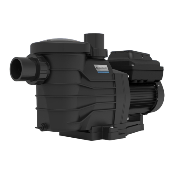
Page 6: System Overview
SMARTFLO SYSTEM OVERVIEW Features: Clear Strainer Basket Lid • Extremely quiet operation. Control Panel Multi-Fit • Super-duty totally-enclosed fan- Unions cooled (TEFC) permanent magnet motor, for long life and premium energy efficiency. • Energy-Star Rated and ETL Listed • NEMA Type 3 Environmental Rating •... -
Page 7: Installation
INSTALLATION Only a qualified individual should install the Variable Speed Pump. Refer to “Pump Warning And Safety Instructions” on pages 3-4 for additional installation and safety information. Pump Configuration The following configurations allow for maximum flexibility during setup: Inside of union accepts 2” ID pipe 10.1”... -
Page 8: Installation Location
Example: A 2.5 inch pipe requires a 12.5 inch (31.8 cm) Installation Location straight run in front of the suction inlet of the pump. This Do not install this pump within an outer enclosure or will help the pump prime faster and last longer. beneath the skirt of a hot tub or spa unless marked accordingly. -
Page 9: Wiring Overview
RISK OF ELECTRICAL SHOCK OR ELECTROCUTION. The Variable Speed Pump must be installed by a qualified individual, service professional, or licensed or certified electrician in accordance with the National Electrical Code and all applicable local codes and ordinances. Improper installation will create an electrical hazard which could result in death or serious injury to users, installers, or others due to electrical shock, and may also cause damage to property. -
Page 10: Control Panel Overview
CONTROL PANEL OVERVIEW 4. Display Mode LED Indicators 1. SPEED Buttons 8. + and - Buttons 6. QUICK CLEAN Button 7. < and > Buttons 5. MENU Display Button 2. MODE SELECT Button 4. START / STOP Button FIGURE 4 If power is connected to the Variable Speed Pump motor, pressing any of the following buttons referred to in this section could result in the motor starting. -
Page 11: Operating The Pump
OPERATING THE PUMP Setting the Clock When the pump is first installed, it is necessary to set the clock. Any daily schedule set by the user must be based on an accurate time setting. To Set the Clock: 1. Before setting the clock, ensure that the pump has power but that its motor is stopped (press STAR/STOP if necessary). 2. - Page 12 Operation Overview (continued) In most cases, setting the pump at the lower speeds for the longer durations is the best strategy to minimize energy consumption. However, conditions may require running the pump at a higher speed for some duration of time each day to maintain proper filtration and achieve satisfactory sanitation. The pool size, presence of additional water features, chemicals used to maintain sanitary conditions, and local environmental factors will impact optimal programming necessary to maximize energy conservation.
-
Page 13: Using The Default Schedule
these things should be taken into consideration when Using the Default Schedule setting the priming speed, however in most cases the pump will not need to run at 3450 RPM to successfully The default schedule is designed to provide enough daily prime itself. -
Page 14: Custom Schedules And Quick Clean
5. Use the “+” and “-” buttons to adjust the daily start time Custom Schedules and Quick Clean for SPEED 1. To customize the run schedule for your Variable Speed 6. Press the “1” button again and the display will change to Pump, the pump must be stopped. -
Page 15: Speed Priorities
Pressing any of the Speed Buttons (“1”, “2”, “3”, “4”, Speed Priorities “Quick Clean”) while the pump is running will act as Since 24 hours is the maximum number of hours in a day, temporary override. It will run the speed and duration the pump schedule will not allow durations exceeding this that is programmed for that button. -
Page 16: Maintenance
MAINTENANCE DO NOT open the strainer pot if Variable Speed Pump fails to prime or if pump has been operating without water in the strainer pot. Pumps operated in these circumstances may experience a build up of vapor pressure and may contain scalding hot water. Opening the pump may cause serious personal injury. -
Page 17: Servicing
SERVICING Always disconnect power to the Variable Speed Pump at the circuit breaker and disconnect the communication cable before servicing the pump. Failure to do so could result in death or serious injury to service people, users or others due to electric shock. -
Page 18: Pump Reassembly
DO NOT run the pump dry. If the pump is run dry, the mechanical seal will be damaged and the pump will start leaking. If this occurs, the damaged seal must be replaced. ALWAYS maintain proper water level. If the water level falls below the suction port, the pump will draw air through the suction port, losing the prime and causing the pump to run dry, resulting in a damaged seal. -
Page 19: Troubleshooting
TROUBLESHOOTING Diagnosing certain symptoms may require close interaction with, or in close proximity to, components that are energized with electricity. Contact with electricity can cause death, personal injury, or property damage. When trouble shooting the pump, diagnostics involving electricity should be cared for by a qualified individual. SCENARIO: POSSIBLE CAUSE: SUGGESTED ACTION:... -
Page 20: Errors And Alarms
Errors and Alarms If an fault is detected, the screen will display the error code text and the Variable Speed Pump will stop running. Disconnect power to the pump and wait until the keypad LEDs have all turned off. At this point, reconnect power to the pump. If the error has not cleared, then troubleshooting will be required. -
Page 21: Replacement Parts
REPLACEMENT PARTS SmartFlo Replacement Parts List Ref. No. Part No. Description Qty. Ref. No. Part No. Description Qty. SF1.0P-SCK Strainer cover Kit SF1.5P-MD Motor Drive for USF1.7P SF1.0P-CO Cover o-ring SF2.0P-MD Motor Drive for USF2.0P SF1.0P-B Strainer Basket SF3.0P-MD Motor Drive for USF3.0P USF1.0P-PH 2”*2”... -
Page 22: Specifications
Specifications Model USF1.0P, USF1.7P, USF2.0P, USF3.0P Overall Ratings Model USF1.0P USF1.7P USF2.0P USF3.0P Input Voltage 230 V Input Frequency Single phase, 50 or 60 Hz Input Current 5.5A Max Continuous Load 1.7HP Speed Range 450 – 3450 RPM Environmental Rating NEMA Type 3 Port Size 2”... -
Page 23: Warranty
2. Should a defect in any item or part covered by the warranty become evident during the warranty's term, CircuPool Products will at its sole discretion repair or replace such item or part. CircuPool Products reserves the right to replace defective parts with new or refurbished parts. - Page 24 SmartFlo Series Owner's Manual Notes:...
Need help?
Do you have a question about the SmartFlo USF1.0P and is the answer not in the manual?
Questions and answers