
Subscribe to Our Youtube Channel
Related Manuals for Mega MEg45DIN


Summary of Contents for Mega MEg45DIN
- Page 1 Universal PQ Monitor MEg45DIN User manual MEgA – Měřící Energetické Aparáty, a.s. MEgA – Měřící Energetické Aparáty, a.s. 664 31 Česká 390 664 31 Česká 390 Czech Republic Czech Republic...
- Page 3 Univerzální PQ monitor MEg45DIN 1/ INTRODUCTION The MEg45DIN universal PQ monitor is designed for measuring and indicating protec- tive functions at the LV level. It transmits measured data and evaluated conditions safely via ETH interface and GSM network even after a power failure of all three phases. It measures three voltages, three currents and two temperatures.
- Page 4 CAT IV / 300 V. It can also be powered with an auxiliary DC supply voltage in the range of 10 to 30 V. The power supply of MEg45DIN contains supercapacitors that provide uninterrupted measurement and remote communication even in the case of short power outages with a total duration of up to 30 s.
- Page 5 With the exception of the WebDator2 program, the mentioned programs, including their manuals, are available at http://www.e-mega.cz/DL/ The MEg45DIN PQ monitor also enables work with third-party SW through the MOD- BUS RTU protocol, or it can transmit measured data as set via EN 60870-5-104 or DLMS/COSEM protocol.
-
Page 6: 3/ Description Of The Instrument
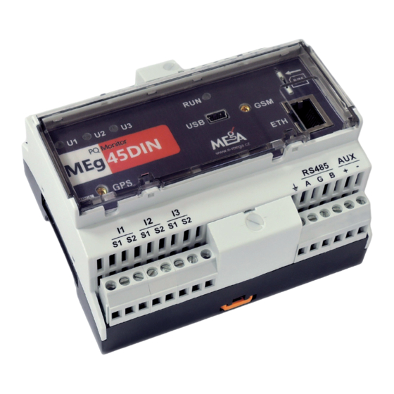
3/ DESCRIPTION OF THE INSTRUMENT 3.1 Design The MEg45DIN monitor in Fig. 1 is designed for fixed installation on a DIN TS35 rail. It is housed in a polycarbonate self-extinguished box measuring 108 × 90 × 61 mm. The structural elements of the MEg45DIN monitor are shown in Fig. 2. Above the monitor panel is a tilting transparent cover that can be sealed to protect the SIM card inside the monitor panel. - Page 7 The panel indicates the type of the MEg45DIN monitor, S/N serial number and QR code with a description of the monitor. On the right side of the MEg45DIN monitor is a rating plate specifying the rated values of measured voltages, currents, frequency, supply...
- Page 8 Měřící Energetické Aparáty Fig. 2: Design elements of the monitor 9 14 RS485 Tab. 1: Description of MEg45DIN elements Group name Description Item Voltage inputs Terminals U1, U2, U3 for direct voltage connection of phases L1, L2, L3 and neutral conductor PEN to Nm terminal...
- Page 9 Universal PQ Monitor MEg45DIN – User manual Item Group name Description DC supply AUX terminals for connecting auxiliary DC supply voltage with voltage a rated value of 12 – 24 V Temperatures Terminals for connecting two Pt1000 sensors measuring tempera- tures T1 and T2...
- Page 10 18 Antenna holes In the indicated areas are holes prepared for antenna cables Examples of variants of rating plates for individual versions of MEg45DIN monitors are shown in Fig. 3. Voltage, power supply and the design are the same for all versions. Volt- age inputs that are also used for three-phase AC power supply have a rated phase voltage value of 230 V.
-
Page 11: Functions Of The Monitor
Universal PQ Monitor MEg45DIN – User manual 3.2 Functions of the monitor The MEg45DIN universal monitor is a class A or S instrument whose measurement methods meet the requirements of class A according to EN 61000-4-30, ed.3. The meas- urement methods and uncertainties of the measured quantities are tested according to EN 62586-2 and the effects of operating conditions according to the procedures spec- ified in EN 62586-1. - Page 12 To synchronize the function of multiple monitors, the positive zero-crossing of the first phase fundamental harmonic voltage can be used. The MEg45DIN universal PQ monitor has secure data transmission with IKEv2/IPsec and L2TP/IPsec protocols. The SSH protocol can be used to connect for management of the Linux Debian system, running on the ARM core of the processor and enabling the implementation of advanced communication and other superstructure functions.
- Page 13 Universal PQ Monitor MEg45DIN – User manual 3.2.2 Measuring functions The scope of measured variables depends on the measurement connection and measure- ment parametrisation. Measured data can be divided into data of continuous phenomena of voltage quality, data of rapid voltage changes, data during one-off voltage phenomena...
- Page 14 Měřící Energetické Aparáty − Average voltage in balanced state after RVC − Maximum absolute difference between U during RVC and balanced voltage RMS1/2 before RVC − Maximum absolute difference of ten-period voltage U at RVC and balanced RMS10 voltage before RVC −...
- Page 15 Universal PQ Monitor MEg45DIN – User manual − Harmonic components of voltage U of order n from 1st to 64th, − Currents I , – average, maximum − THD current harmonic distortion factor − Current harmonics I of order from 1st to 64th, −...
- Page 16 Měřící Energetické Aparáty Data of electric meter function for output and each phase from the beginning of factory setting and from the start of measurement: − Active and reactive energy E QC/P+ QL/P+ QC/P- QL/P- Data of the function of active energy measurement during rapid changes of flow direction for the terminal and each phase from the beginning of the measurement according to the measurement parametrization: −...
- Page 17 Universal PQ Monitor MEg45DIN – User manual Fig. 4: Examples of setting protection and signalling functions Two-stage undervoltage protection function In the function input, the user sets the limit of the 1st stage and the lower limit of the 2nd...
- Page 18 Měřící Energetické Aparáty With the undervoltage protection function, the instrument continuously evaluates inde- pendently for each phase whether all evaluated voltages are under the undervoltage limit within the detection time. If so, the protection function activates. The instrument records the activation time, the affected phase, the undervoltage value at the moment of protec- tion activation as well as the course of RMS½...
- Page 19 Universal PQ Monitor MEg45DIN – User manual Each evaluation of voltage unbalance of a value lower than the set limit resets the detec- tion time. A voltage drop of any phase below the blocking limit blocks the protection function. Function of protection according to current unbalance...
- Page 20 TN-S networks and to the PEN conductor in TN-C networks. The MEg45DIN monitor is powered by the voltages of the measuring voltage inputs. It also has an auxiliary (AUX) DC power supply with a rated value of 12 – 24 V connected between terminals + and –.
- Page 21 S1 and S2. The S1 input terminals must always be grounded. The connection of the common terminals in MEg45DIN in safety class II is shown in Fig. 5. The common connection pole S is connected to the negative pole of the auxiliary DC power supply.
- Page 22 Měřící Energetické Aparáty Fig. 5: Interconnection of common terminals in MEg45DIN PT1000 MEg45DIN S1 S2 S1 S2 S1 S2 Sensors RS485 12V-24V PT1000 MEg45DIN S1 S2 S1 S2 S1 S2 RS485 12V-24V 5A/1A For measuring currents in structurally complicated types of collecting points (doubled busbar, low distances between busbars, etc.) and in CAT IV 300 V areas, it is advisable...
- Page 23 24 mm and 36 mm. The wiring is shown in Figure 9. LCT transformers have a standard output voltage of 225 mV, 150 mV and 22.5 mV. In this case, the MEg45DIN monitor has current inputs with the corresponding voltage values. LCT transformers can only be installed on insulated conductors at air and surface distances from live parts meeting the safety requirements of the installation site.
- Page 24 The connection of local communication between the measuring and control system and a group of MEg45DIN monitors using the RS485 interface is shown in Fig. 15. One RS485 interface with the MODBUS TCP allows communication with up to 30 devices.
- Page 25 Universal PQ Monitor MEg45DIN – User manual Fig. 6: Connection of MEg45DIN in a transformer station, CAT IV 300V, current transformers with I = 5 A Fuse switch-disconnector Cylindrical fuse 1 A RS485 Consumption...
- Page 26 Měřící Energetické Aparáty Fig. 7: Connection of MEg45DIN in a LV TN-S type network, with fuse disconnec- tors in voltage circuits and current transformers MTPD.51 with I = 1 A Fuse switch-disconnector Cylindrical fuse 1 A RS485 Fuse switch-disconnector Cylindrical fuse 1 A...
- Page 27 Universal PQ Monitor MEg45DIN – User manual Fig. 8: Connection of MEg45DIN in a LV TN-C type network, with fuse dis- connectors in voltage circuits and current measurement by AMOS/1A sensors, category CAT IV 300 V L3 PEN Fuse switch-disconnector...
- Page 28 Měřící Energetické Aparáty Fig. 9: Connection of MEg45DIN in a LV TN-S type network, current measurement by LCT Fuse switch-disconnector Cylindrical fuse 1 A RS485 Fuse switch-disconnector Cylindrical fuse 1,0A DC power supply 10 to 30 V Consumption...
- Page 29 Universal PQ Monitor MEg45DIN – User manual Fig. 10: Connection of MEg45DIN in a LV TN-C type network, current measure- ment by TORv or TORm toroids, category CAT IV 300 V Fuse switch-disconnector Cylindrical fuse 1 A RS485 Fuse switch-disconnector...
- Page 30 Měřící Energetické Aparáty Fig. 11: Connection of MEg45DIN monitor with current measurement by TORm toroids connected in secondary current circuits of current transformers Fuse switch-disconnector Cylindrical fuse 1 A RS485 k l k l TORm TORm TORm Consumption...
- Page 31 Universal PQ Monitor MEg45DIN – User manual Fig. 12: Connection of MEg45DIN in a LV TN-S type network, current measurement by AMOSm sensors, category CAT IV 300 V Fuse switch-disconnector Cylindrical fuse 1A RS485 Fuse switch-disconnector Cylindrical fuse 1A DC power supply...
- Page 32 Měřící Energetické Aparáty Fig. 13: Connection of MEg45DIN two-stage inputs and temperature sensors 12V, 24V U =+5V RS485 Fig. 14: Connection of load at a LV level in a CAT IV 300 V environment to the OUT output switching contact of the monitor through the REL IV/DC relay...
- Page 33 RS485 120Ω Local measuring and control system max. 30m, max. 30 addresses Fig. 16: Connection of GPS and GSM antennas and connection of MEg45DIN to an Ethernet network communication synchronization Ethernet RS485 RJ45 – ETH connector Signal TX+ on pin 1...
- Page 34 Měřící Energetické Aparáty Fig. 17: Communication of MEg45DIN monitors via the ETH interface and Switch unit RS485 RS485 Fig. 18: Data transmission and time synchronization of remote electric meters via a transparent channel of GSM communication of MEg45DIN GSM communication...
- Page 35 • When the MEg45DIN universal PQ monitor is used in a different way than specified by the manufacturer, the protection provided by MEg45DIN may be impaired.
- Page 36 • Maintenance and repairs of monitors may only be carried out by the manufacturer or service organizations authorized by the manufacturer. • It is not permitted to use other accessories than those included in the MEg45DIN monitor set delivery. Caution...
- Page 37 1. Install the MEg45DIN universal monitor on a TS 35 DIN rail, preferably in a hori- zontal position. Secure its position using locks 16 in Fig. 2.
- Page 38 - terminal of the monitor. To power only the MEg45DIN monitor, use 10×38gG cylinder fuses with a rated value of 1.0 A. To power the MEg45DIN unit and three AMOS/1A converters, use fuses with a rated value of 4.0 A.
- Page 39 A3 (+U ) contacts of all three converter units to the input current terminals S1 and S2 of the I1, I2 and I3 current inputs of the MEg45DIN monitor, grounding of the -U ,k terminals and connecting of power supply to the converter units is shown in Fig.
- Page 40 Měřící Energetické Aparáty of the loop in the loop closure deep enough to be locked against accidental ex- traction by the lock. When installed on the ribbon steel of a LV busbar, fix the position of the loop on the busbar using a clamp with a clearance of 5 mm or 10 mm. Mount the clamp on the busbar at the site of installation, insert the closed closure of the flexible sensor loop in its cavity so that the closure is guarded against accidental opening and, moreover, the body of the clamp reduces direct electric and thermal contact...
- Page 41 8. The galvanically free switching contact of the external device powered by the inter- nal 5 V voltage of the MEg45DIN monitor in Figure 13 is connected to terminals 1 and 2 of the IN input. If the switching contact is grounded at one pole, this pole must be connected to terminal 2 of the IN input, which is connected to the RS485 interface shield via the common conductor G in the monitor.
- Page 42 DC relay in DIN rail design with CAT IV 300 V overvoltage category between input and output circuits. 10. Fig. 15 to Fig. 18 show the basic connection of MEg45DIN with local and remote communication. Figure 15 shows local communication of monitors via the RS485 interface with a local measuring and control system using a shielded twisted pair.
- Page 43 3. Use a USBmini communication cable to connect the inspection computer to the MEg45DIN monitor. The main window will display information on the SW and FW version. The bar in the main window displays the type and serial number of the connected monitor, see Figure 21.
- Page 44 Měřící Energetické Aparáty 4. In the main bar, select “Měřidlo” (Meter) according to Fig. 22. This shows the values of the connected phase voltages and phase currents in the Samples view. To check the correct direction of current connection, correct direction of phase voltage rotation and correct assignment of phase currents to phase voltages, press the Test button.
- Page 45 Universal PQ Monitor MEg45DIN – User manual A check of the correct connection of a GSM network antenna with sufficient GSM network signal intensity is indicated by a highlighted GSM network pictogram at the end of the main bar of the program. Click on the pictogram to display information on the GSM network signal intensity at the antenna installation location, see Fig.
- Page 46 To protect the AUX auxiliary DC power supply and the trio of AMOS/1A flexible sen- sors, use 10×38gG 4.0 A cylinder fuses. 9/ DISPOSAL When the service life of the MEg45DIN universal monitor is over, it must be recycled at waste disposal sites according to rules for electronic waste disposal. 10/ WARRANTY...
- Page 47 The warranty becomes void if the user carries out unauthorized modifications or changes on the MEg45DIN monitor, if the user connects the monitor incorrectly or if the monitor has not been operated in accordance with technical conditions. Defects on the MEg45DIN monitor originating during the warranty period shall be claimed by the user with the manufacturer.
- Page 48 − GPS time synchronisation module − GSM remote communication module − LTE/GPS PUCK, mounting antenna AO-AKOM-36SS/MEgA − GPS PUCK, mounting antenna GPS PUCK AP-AGPS-36/MEgA − LTE rod, rod antenna LTE AO-ALTE-G124S/MEgA − GPS magnet, GPS magnetic antenna AP-A20C-M5RA/MEgA − GPS extension cable / 10 m with thicker insulation with a length of 2.5 m...
- Page 49 Universal PQ Monitor MEg45DIN – User manual Tab. 2: Current ranges of LCT split-core transformers (× = yes, ⁄ = no) Primary current Diame- ter [mm] 10 A 20 A 60 A 75 A 100 A 120 A 200 A 300 A 400 A 500 A 600 A ×...
- Page 50 The MEg45DIN universal monitor meets, according to EN 61010-2-30, the measuring category and the overvoltage category of CAT IV 300 V. The MEg45DIN universal monitor is classified, according to EN 62586-1, as PQI-A- FI1-H or PQI-S-FI1-H. The development and production of the monitor is in conformity with ISO 9001, ISO 14001:2005, OHSAS 18001:2008, ISO/IEC 27001:2014.
- Page 51 Universal PQ Monitor MEg45DIN – User manual Protection = 160 V to 300 V , inputs: 3 cylinder fuses 10 × 38gG 1.0 A fuse disconnector OPVP-3 = 12 V to 24 V , AUX: 2 cylinder fuses 10 × 38gG 1.6 A fuse disconnector OPVP-2 2 cylinder fuses 10 ×...
- Page 52 Input impedance of current inputs: 2 MΩ / 47pF The current measurement parameters of the AMOSm + MEg45DIN set are listed in the technical data of Chapter “Current sensors of the MEg45DIN universal PQ monitor”. Active power, reactive power, PF, energy Active power ±0.5 % M.V.
- Page 53 Universal PQ Monitor MEg45DIN – User manual IN input contacts Number: 1 galvanically free Internal supply voltage: Rated external supply voltage: 12 V to 24 V Max. resistance of contact external circuit: 100 Ω OUT output contacts Number: 1, galvanically free switching contact...
- Page 54 Měřící Energetické Aparáty GSM communication SIM card type: nano SIM in a 115S-AC1 slot Technology: LTE Cat. 4, HSPA+, EDGE, GPRS (class B, CS1 to CS4) Frequency bands [MHz]: 4G B1 (2100), B3 (1800), B7 (2600), B8 (900), B20 (800) B1 (2100), B8 (900) B3 (1800), B8 (900) Watchdog for modem restart in case of communication loss...
- Page 55 Class S Class A RMS1/2 Note: According to EN 61557-12, the MEg45DIN universal monitor is a measuring device of the PMD SD class (performance measuring and monitoring device) with current measurement by means of sensors and direct voltage measurement. It integrates the functions of recording, electric energy measurement, voltage...
- Page 56 Měřící Energetické Aparáty Measurement uncertainty and measuring ranges of voltage quality parameters during test conditions 1, 2 and 3 according to standard EN 61000-4-30 ed. 3 With uninterruptible power supply, duration depends on the external power supply...
- Page 57 Universal PQ Monitor MEg45DIN – User manual Overview of evaluated quantities in recorder function Quantity Symbol Effective voltage F, S F, S Voltage harmonics – 1st to 64th F, S F, S harmonic 64.h Overall harmonic distortion of F, S...
- Page 58 Měřící Energetické Aparáty Quantity Symbol Active power (1st harmonic) F, S F, S Reactive power (1st harmonic) F, S F, S Apparent power (1st harmonic) F, S F, S Unbalance power (1st harmonic) F, S F, S Active energy – consumption F, S F, S Active energy –...
- Page 59 [2] User Description of MEgA Explorer, www.e-mega.cz/DL [3] User Description of MEgA Merci Multi, www.e-mega cz/DL [4] User Description of the MODBUS TCP of MEgA Instruments, www.e-mega.cz/DL [5] User Description of the EN 60870-5-104 Protocol of Instruments Upon Request [6] User description of WebDatOr2, on request 14/ MANUFACTURER MEgA –...
- Page 60 Měřící Energetické Aparáty AGSM AND AGPS ANTENNAS OF THE MEg45DIN UNIVERSAL MONITOR Antennas AO-AKOM-36SS/MEgA AO-ALTE-G214S/MEgA GSM/UMTS/LTE/GPS GSM/UMTS/LTE Frequency bands MHz 800 / 900 / 1700 / 1800 700 / 800 / 900 / 1700 1900 / 2100 / 2600 1800 / 1900 / 2100 / 2600 2700 /1757.42...
- Page 61 Universal PQ Monitor MEg45DIN – User manual Antennas AP-AGPS-36/MEgA AP-A20C-M5RA/MEgA Frequency bands MHz 1575.42 1575.24 Gain 30 dBi 32 dBi VSWR < 2.0 : 1 < 2.0 : 1 Impedance 50 Ω 50 Ω Direction omnidirectional omnidirectional HPBW H 360° V 30°...
- Page 62 Měřící Energetické Aparáty CURRENT SENSORS OF THE MEg45DIN UNIVERSAL PQ MONITOR Technical data of the MTPD.51 split-core current transformer Rated primary current I 400 A, 600 A, 1000 A Rated secondary current: Rated frequency: 50 Hz Frequency range: 42.5 Hz to 69 Hz Rated load: 2.5 VA...
- Page 63 Universal PQ Monitor MEg45DIN – User manual Safety class: Weight: 0.5 kg Outer dimensions: 100 × 95 × 29 mm Dimensions of transformer window: 52 × 33 mm Supply cable (optional): Maximum length of supply cable: 10.0 m Supply cable diameter: 7.0 mm...
- Page 64 Měřící Energetické Aparáty Technical data of AMOS/1A flexible sensors The flexible AMOS/1A sensor consists of an AMOSm sensor with the specified length of measuring loop with shielded cable and of a converter unit with the output voltage of 1 A. Rated input alternating current I 100 A, 160 A, 250 A 1) 2)
- Page 65 Universal PQ Monitor MEg45DIN – User manual Consumption at I and R = 2.5 Ω: ≤ 5 W Idle consumption: 70 mA at U = 12 V 50 mA at U = 24 V Total efficiency at I and R = 1.0 Ω:...
- Page 66 Měřící Energetické Aparáty Technical data of TORv and TORm toroids TORv TORm Rated input current I 10 A, 50 A 1 A, 5 A Output voltage 225 mV , 150 mV , 22.5 mV Measuring range: 5 % to 120 % I Measurement error at f = 50 Hz 0.5 % from the range Harmonic measurement uncertainty...
- Page 67 Universal PQ Monitor MEg45DIN – User manual TORm toroid TORm CATIV/300V S/N 00000 TORv toroid TORv CATIV/300V S/N 00000...
- Page 68 Měřící Energetické Aparáty Technical data of LCT split-core current transformers Rated primary current I LCT-10 5 A, 20 A, 60 A, 75 A LCT-16 100 A, 120 A, 200 A LCT-24 100 A, 200 A, 400 A LCT-36 300 A, 400 A, 500 A, 600 A Rated secondary voltage 225 mV, 150 mV, 22.5 mV Precision class:...
- Page 69 Universal PQ Monitor MEg45DIN – User manual LCT-10 split-core transformer, hole diameter 10 mm LCT-16 split-core transformer, hole diameter 16 mm...
- Page 70 Měřící Energetické Aparáty LCT-24 split-core transformer, hole diameter 24 mm LCT-36 split-core transformer, hole diameter 36 mm...
- Page 71 Universal PQ Monitor MEg45DIN – User manual Technical data of the loops of flexible sensors AMOSm / short, AMOSm / standard a AMOSm / long in a measuring set with the MEg45DIN universal PQ monitor SW setting of the rated value.
- Page 72 Měřící Energetické Aparáty Loop diameter: 8 mm Enclosure free end diameter: 10 mm Permissible loop bending radius: > 20 mm Cable length: Flexible sensor AMOSm/long (loop length 60 cm) AMOSm/long/45PAN CATIV/300V S/N 00000 Flexible sensor AMOSm/standard Flexible sensor AMOSm/short (loop length 40 cm) (loop length 20 cm) AMOSm/short/45PAN AMOSm/standard/45PAN...
- Page 73 Universal PQ Monitor MEg45DIN – User manual Technical data of CAT IV / 300 V relay Input circuit; terminals A1, A3 REL IV DC Maximum and minimum control voltage: 30 V / 10 V Minimum withstand voltage: Control DC voltage...
- Page 74 Měřící Energetické Aparáty General data Dimensions: 90 × 60 × 18 mm Relay installation: TS35 DIN rail Number of cycles: 10 · 10 Switch on/opening time of REL IV DC: 8 ms / 5 ms Switch on/opening time of REL IV AC: 10 ms / 15 ms Consumption: ≤...
- Page 75 Universal PQ Monitor MEg45DIN – User manual ANNEX Examples of the evaluation of data measured by the MEg45DIN program MEgA Explorer Measuring function Záznamník (Recorder) Average and extreme values with time data, voltage, currents, active and reactive power Time course of average, minimum and maximum voltage, average and maximum currents...
- Page 76 Měřící Energetické Aparáty Measuring function Napěťové jevy (Voltage phenomena) Standard parameters of voltage phenomena Contingency table of voltage drops Graph of the appliance resistance against voltage phenomena...
- Page 77 Universal PQ Monitor MEg45DIN – User manual Record of phenomena, example of RMS1/2 courses and oscillographic records of phase voltages and currents...
- Page 78 Měřící Energetické Aparáty...
- Page 79 Universal PQ Monitor MEg45DIN – User manual Measuring function Elektroměr (Electric meter) Total energy of three phases and individual phases with a phasor diagram Quarter-hour, hourly, daily, weekly and monthly table of phase active energy...
- Page 80 Měřící Energetické Aparáty Measuring function Kvalita napětí (Voltage quality), selected examples Graphic overview of continuous voltage quality parameters throughout the entire period of measurement Weekly evaluation of voltage quality Courses of phase voltage quality Plt flickers...
- Page 81 12/ Technical parameters ..................49 13/ Literature ......................58 14/ Manufacturer ..................... 58 AGSM and AGPS antennas of the MEg45DIN universal monitor ......59 Current sensors of the MEg45DIN universal PQ monitor ........61 Technical data of the MTPD.51 split-core current transformer ........ 61 Technical data of flexible AMOS/1A sensors ............
- Page 82 Měřící Energetické Aparáty...
- Page 84 Universal PQ Monitor MEg45DIN User manual MEgA – Měřící Energetické Aparáty, a.s. 664 31 Česká 390 Czech Republic www.e-mega.cz Edition: 02/2024...
Need help?
Do you have a question about the MEg45DIN and is the answer not in the manual?
Questions and answers