
Subscribe to Our Youtube Channel
Related Manuals for FLUXION BIOFLUX 1000Z

Summary of Contents for FLUXION BIOFLUX 1000Z
- Page 1 FLUXION BIOSCIENCES INC. www.fluxionbio.com ™ BIOFLUX 1000Z Automated microfluidic system for live-cell imaging USER’S GUIDE Revision F...
-
Page 2: Table Of Contents
FLUXION BIOSCIENCES BIOFLUX™ BioFlux 1000z - User’s Guide Table of Contents Chapter Introduction Hardware Overview BioFlux Controller Pneumatic Connections Electrical Connections External Gas Supply Software Setup and Manual Mode Experiments Installation - Setup and Calibration BioFlux Control Module Modes Manual Image Acquisition... - Page 3 FLUXION BIOSCIENCES BIOFLUX™ Warranty Warranty Information CE Declarations End User License Agreement BIOFLUX 1000Z REV F...
-
Page 4: Chapter 1 Introduction
BIOFLUX™ CHAPTER 1: INTRODUCTION Thank you for your purchase of a BioFlux 1000z System for automated live cell analyses under controlled shear flow. The BioFlux 1000z offers an unparalleled ability to run physiologically-relevant biological assays with the throughput and convenience of conventional microtitire plate formats. - Page 5 Please refer to the supplemental hardware manuals which were provided to you during the installation of the system for additional installation and operation information. 4. Fluxion Application Support Fluxion Application Specialists are available to assist with hardware, software and biological application questions. Call or email using the contact information on this page. BIOFLUX 1000Z...
- Page 6 FLUXION BIOSCIENCES BIOFLUX™ BIOFLUX PLATE FLUIDIC LAYOUTS 24-well BioFlux Plate (0-20dyn/cm 48-well BioFlux Plate (0-20dyn/cm or 0-200 dyn/cm BIOFLUX 1000Z REV F...
-
Page 7: Hardware Overview
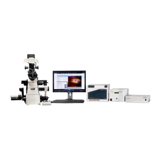
FLUXION BIOSCIENCES BIOFLUX™ CHAPTER 2: BIOFLUX 1000Z HARDWARE OVERVIEW Label Component BioFlux Imaging Station CCD Camera Automated Stage AutoFocus Module PC Workstation BioFlux Controller Fluorescence Controller Main Controller BioFlux 1000z Interface BIOFLUX 1000Z REV F... - Page 8 FLUXION BIOSCIENCES BIOFLUX™ BIOFLUX 1000Z HARDWARE DETAILS Component Description Power up and handling instructions BioFlux Imaging Station The BioFlux Imaging Station is The power switch is located on built around a high end Nikon the front of the controller. Press inverted microscope.
- Page 9 If power is lost to this component, communication to the computer and peripheral components may be disrupted. BioFlux 1000z Interface The BioFlux 1000z Interface There are no powered distributes pneumatic pressure components on the Interface. to the BioFlux Plates.
-
Page 10: Bioflux Controller
Connecting Tubing Harness from the Interface to the Controller A Tubing Harness is provided which contains 6 or 8 tubes bundled together. The 24-well plate interface has 6 tubes, while the 48-well plate interface has 8 tubes. BIOFLUX 1000Z [10] REV F... - Page 11 At this point you have made all the required pneumatic connections. Note that the 24-well plate interface has a different tubing harness and connections. If you have multiple Interfaces, you can swap between the two by removing the tubing from the fluid trap on the back panel. BIOFLUX 1000Z [11] REV F...
-
Page 12: External Gas Supply
3. Connect the BioFlux power supply output cable to the back panel socket labeled “Power Supply” and plug the other end in to a power outlet. ◦ To prevent damage to the accessory heater, do not set the temperature controller over 50 BIOFLUX 1000Z [12] REV F... - Page 13 2. Connect the male fitting to the female port on the rear of the BioFlux 1000z Controller as shown in the figure.
-
Page 14: Software Setup And Manual Mode Experiments
PSI/Volt, Regulator 2 Offset) in the dialog box. These values can be found on the back of the BioFlux 1000z Controller. When finished, click Apply and close the dialog box. If you do not enter the calibration information, the software will display a reminder. - Page 15 FLUXION BIOSCIENCES BIOFLUX™ Setting Fluid Properties BioFlux 1000z Software provides support for managing the fluid properties of commonly used reagents, media, and compounds you might use. It is important to note that shear stress is dependent on viscosity, which means that you will want to take care to input the correct fluid properties for each experiment.
- Page 16 You can change an interval by selecting it from the table, changing the settings, and then clicking the ‘Update’ button. The ‘Remove’ button will remove an interval from the protocol. Once the protocol is completed, click ‘Save As’ to create the file. BIOFLUX 1000Z [16] REV F...
- Page 17 Note that this tracking system is based on calculated flow rates and does not have a sensor to detect well volumes. Care should be taken to monitor the wells as they get close to empty. BIOFLUX 1000Z [17] REV F...
- Page 18 Pause/Abort buttons as needed. When the sequence is completed, you can use the ‘Save Log’ button to save the sequence details in a CSV file (readable by Microsoft Excel or similar application). BIOFLUX 1000Z [18] REV F...
- Page 19 Upon installation by an authorized Fluxion representative or distributer, the BioFlux 1000z Imaging Components will be set up for your experiments and ready to collect data. This section explains how to capture images using a BioFlux Plate and the BioFlux 1000z. 1. Launch BioFlux Montage software. Launch the camera capture icon (right, Control Panel).
- Page 20 Please use the camera control panel OR the Multi-dimensional acquisition/MDA (explained in section XX). Do not open both camera controls at once. You will experience inconsistent control of the exposure times under this operating mode. BIOFLUX 1000Z [20] REV F...
-
Page 21: Running Experiments In Automated Mode
BIOFLUX™ CHAPTER 5: RUNNING EXPERIMENTS IN AUTOMATED MODE The BioFlux 1000z system was designed to integrate the BioFlux control module with the BioFlux Montage software to enable simultaneous flow protocols and image capture. This entails full automation of the flow protocols, stage positions, illumination source, image acquisition and data logging. - Page 22 Within the Main Panel, you can select timelapse, stage positions, illumination settings, and journals (these enable the synergy between the BioFlux controller module and Montage). As you click down through the choices on the left and select parameters you are setting up your BioFlux 1000z experiment. BIOFLUX 1000Z...
- Page 23 1,1; 1,2;1,3 and so on. Embedded within the BioFlux Software are preset stage lists for each plate which can be loaded using the ‘Load…’ tab in the Stage menu. Preloaded stage lists can be found in ProgramFiles/Montage/app/mmproc/data/stage lists BIOFLUX 1000Z [23] REV F...
- Page 24 If you want to have no wait time between stage list acquisitions, populate the time interval with “0”. In this case, the timelapse will proceed without delay. BIOFLUX 1000Z [24] REV F...
- Page 25 (automates a sequence of operations). Never load journals manually; this may cause issues with instrument synchronization. • The Display tab controls how you view the images while the automated acquisition proceeds. • The Summary tab displays all the parameters you have set for your experiment. BIOFLUX 1000Z [25] REV F...
- Page 26 Select the fluids being used from the pull down menus. IF YOU ARE RUNNING AN AUTOMATED WORKFLOW DO NOT PUSH ‘START’ IN THE BIOFLUX XONTROL MODULE – THE MDA MODULE WILL START THE PROTOCOL FOR YOU (read below). BIOFLUX 1000Z [26] REV F...
- Page 27 4. Adjust stage while using the oculars to ~channel 4 number and arrow marker. 5. Push the ‘Live’ Button on the SRA –this gives a live preview with crosshairs. 6. Line the point of the arrow up with the crosshairs as shown below. BIOFLUX 1000Z [27] REV F...
- Page 28 22 arrow. If you are using the 24 well plate use the ‘8,2’ position to get close to the second calibration point which is the number 8 arrow. 9. Record the ‘Y’ coordinate as seen in the MDA. BIOFLUX 1000Z [28] REV F...
- Page 29 ‘Y’ coordinate] – in the for the ‘X’ & ‘Y’ in Point 2. Go to the ‘Update Stage Positions’ Tab in the SRA and push ‘apply’ to MDA Stage List. The calibration will then be applied to the stage list for your acquisition. 11. Close the SRA. You are ready to begin automated data acquisition. BIOFLUX 1000Z [29] REV F...
- Page 30 Autofocus can be used to focus within the Z-dimension during the MDA in concert with all the other hardware controlled by the MDA. Autofocus is found within the MDA “wavelengths” tab. Configuration of autofocus can be set up by clicking the ‘Configure’ button which launches the menu ‘MDA:Autofocus’. BIOFLUX 1000Z [30] REV F...
- Page 31 Highlight the stage position you are working on and then push the ‘+’ button located on the left hand side of the stage list. A dialog box will pop up asking you if you want to change the position – click’ Yes’ Repeat for the remainder of stage positions. BIOFLUX 1000Z [31] REV F...
- Page 32 Now the stage position contains the correct ‘Z’ for data acquisition. If you remove the plate from the stage you may have to adjust the focus again. Note that focal planes for brightfield and fluorescence can be different. BIOFLUX 1000Z [32] REV F...
-
Page 33: Application And Biology Guide
The BioFlux Pressure Interface sits on top of the BioFlux Plates and creates a seal around each individual well. The interface supplied with the BioFlux 1000z system clamps down on the stage or on the extra supplied base. Align the inserts hanging down from the bottom side of the interface in the holes on the base, slide the interface over the plate until you can push it anymore and clamp the levers down to tighten. -
Page 34: Plate Preparation
To prime or coat a low-shear (0-20 dyn) bcxx 48-well plate follow these steps below: • Load at least 40 µL of PBS (or substrate solution) to the outlet well • Place the BioFlux interface on the plate and ensure a snug/tight seal BIOFLUX 1000Z [34] REV F... -
Page 35: Coating The Channels
Note that different cell types may require different coatings to create optimal adhesion to the glass cover slip bottom of the BioFlux Plate. BIOFLUX 1000Z [35] REV F... -
Page 36: Establishing Shear Flow
Therefore, for runs exceeding several minutes, it is recommended practice to add extra volume to the active well. BIOFLUX 1000Z [36] REV F... -
Page 37: Data Analysis
Creates and manipulate hand-traced regions of interest. Single Line Creates single line regions. Multi-Line Creates lines consisting of more than two or more straight-line segments. Traced Line Creates freehand lines. Auto-Trace Creates regions by automatically tracing objects. Region BIOFLUX 1000Z [37] REV F... - Page 38 (2) Exclusive, with the gray values equal to or above the upper threshold limit, and those equal to or below the lower threshold limit, highlighted by the red overlay, and (3) Off. BIOFLUX 1000Z [38]...
- Page 39 D. Calibrate distances (Measure Menu) This tool can be used to set pixels in an image to real world measurements. Once your system is installed each objective will be calibrated with a stage micrometer to set these values. BIOFLUX 1000Z [39] REV F...
- Page 40 When you launch the calibrate menu, you are given the option to apply the preset calibrations to your image or create new calibrations by using the ‘Calibrate by region’ button which provides a ruler which you can use to line up with your micrometer. BIOFLUX 1000Z [40] REV F...
- Page 41 Distance measurements can be logged to a data log, which you can open and configure from within the Calipers dialog box. Note: To express the distance measurement in "real" units, be sure to apply the Calibrate Distances command before stamping the image or logging the measurement. BIOFLUX 1000Z [41] REV F...
-
Page 42: Integrated Morphometry Analysis
Superficially, the Measuring and Classifying parameter lists that appear in the Parameters List Box as a result of this selection will look identical. However, they serve very different functions. When BIOFLUX 1000Z [42] REV F... - Page 43 Teach allows you to add the parameters of objects you click in the image window to the classifier filter criteria. Find allows you to find objects in the object measurement data table, or find their histogram bin, by clicking an object in the image window, and vice versa. BIOFLUX 1000Z [43] REV F...
- Page 44 (*.cls) for a particular image. This option is journalizable. Preferences Displays the Montage Preferences dialog box with the Measure Objects page selected. This is the same page as is displayed when you choose Preferences from the Edit menu. BIOFLUX 1000Z [44] REV F...
- Page 45 Filter Range for the measurement parameter represented on the X-axis. Objects that fall outside of the filter range will revert to the red thresholding overlay (or will change to a blue object BIOFLUX 1000Z [45] REV F...
- Page 46 Draw Failed Classifier Objects in the Measure Objects page of the Preferences dialog box); objects that stay within the filter range will retain the green object overlay. Close Closes the dialog box. BIOFLUX 1000Z [46] REV F...
- Page 47 2. Open the first image in the stack. You can threshold and arrange the IMA for the image before starting, however there is an interactive threshold that is part of the automation as well as default IMA settings. BIOFLUX 1000Z [47]...
- Page 48 3. Open the Analysis Taskbar from Program files/Montage/Bioflux/Taskbars or if the main taskbar is open – retrieve it from there. 4. Click on the routine you are interested in running. 5. Click through the dialog boxes as they pop up. BIOFLUX 1000Z [48] REV F...
- Page 49 FLUXION BIOSCIENCES BIOFLUX™ Interactive threshold settings – you can adjust the threshold at this point. Use Current IM settings – refers to when you have set the IMA before you started the analysis. BIOFLUX 1000Z [49] REV F...
- Page 50 Parameters shown in the log file can be chosen in the IMA if you want just a few selected measurements displayed. Here is an example summary log: Parameters important to the IMA selected are shown such as the total and average intensity, object counts and so on. BIOFLUX 1000Z [50] REV F...
- Page 51 • Remove the tubing from the controller side of the vapor trap leaving the filters attached to the vapor trap. • Move entire assembly, vapor trap included, and the paper mat to a Biosafety cabinet. BIOFLUX 1000Z [51] REV F...
- Page 52 It may be necessary to periodically order replacement parts and increase the frequency of preventative maintenance. The parts which may need to be replaced are available from Fluxion or an authorized regional representative, and include: tubing sets, filters, tubing connectors, interface gaskets and vapor trap inserts.
- Page 53 If still no connection, go to ‘Simulation’ mode. System Menu – Data Acquisition Setup and see if there is a device recognized in the menu. If no device is recognized, check that the USB port is 2.0. BIOFLUX 1000Z [53] REV F...
- Page 54 Tips and Tricks Instrument control: Disable live updates on PC which may restart the computer controlling the BioFlux 1000z. Also configure power saving settings so that the computer will not shut down or hibernate during BioFlux operation- especially important for overnight experiments. When possible, disable any connection to the internet or intranet.
- Page 55 Sometimes a bubble is lurking in the wells of interest or the serpentine from the priming process. Therefore before starting an experiment, always check around the well-microfluidic interface and in the serpentine for residual bubbles. Deal with them as above (plates). BIOFLUX 1000Z [55] REV F...
- Page 56 Fluxion Biosciences warrants BioFlux instruments against defects in materials and workmanship for a period of one year from date of installation. During the warranty period, Fluxion will, at its option, repair or replace products that prove to be defective. Fluxion warrants that its software and firmware designed for use with a CPU will execute its programming instructions when properly installed on that CPU.
- Page 57 Model No.: 1000z Serial No: <As marked on unit> The undersigned hereby declares, on behalf of Fluxion Biosciences, Inc. of Alameda, CA, that the above- referenced product, to which this declaration relates, is in conformity with the provisions of: Requirement: Standard:...
- Page 58 FLUXION BIOSCIENCES BIOFLUX™ Declaration of Conformance – BioFlux Imaging Station BIOFLUX 1000Z [58] REV F...
- Page 59 FLUXION BIOSCIENCES BIOFLUX™ Declaration of Conformance – Power Supply BIOFLUX 1000Z [59] REV F...
- Page 60 FLUXION BIOSCIENCES BIOFLUX™ Declaration of Conformance – Fluorescence Module BIOFLUX 1000Z [60] REV F...
- Page 61 BioFlux Montage Software Product in accordance with Fluxion’s then-current return procedures. 1. The FLUXION Software Product is supplied to End User with a parallel port software protection key (a “Dongle”). The FLUXION Software Product will not operate on a Fluxion Product to which a Dongle has not been attached.
Need help?
Do you have a question about the BIOFLUX 1000Z and is the answer not in the manual?
Questions and answers