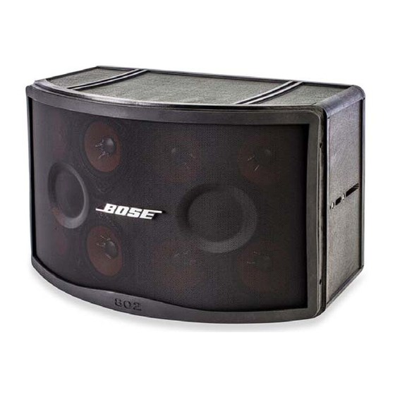
Bose 802 IV Series Service Manual
Loudspeaker
Hide thumbs
Also See for 802 IV Series:
- Installation manual (24 pages) ,
- Installation manual (2 pages) ,
- Installation manual (32 pages)
Summary of Contents for Bose 802 IV Series
- Page 1 ® Series IV Loudspeaker ©2022 Bose Corporation Service Manual Reference Number 739058-SM Rev. 01...
-
Page 2: Table Of Contents
THIS DOCUMENT CONTAINS PROPRIETARY INFORMATION OF BOSE CORPORATION WHICH IS BEING FURNISHED ONLY FOR ® THE PURPOSE OF SERVICING THE IDENTIFIED BOSE PRODUCT BY AN AUTHORIZED BOSE SERVICE CENTER AND SHALL NOT BE REPRODUCED OR USED FOR ANY OTHER PURPOSE. SPECIFICATIONS External dimensions: Single speaker: 13.5"... -
Page 3: Product Description And Accessories
Pro Portable product to a Pro Installed product. The loudspeaker enclosure has been re-designed to include two additional inserts per side in order to better facilitate hanging them in system installs using the newly designed U-bracket from Bose ®... -
Page 4: Packaging Part List
PACKAGING PART LIST Item Number Description Part Number Qty. Note CARTON, RSC, 275DW, 802 SERIES IV 738289-0010 PACKING, ASSY, DC, PE, 275C, 802 SERIES IV 738288-0010 PACKING, INSERT, DC, 802 SERIES IV 739762-0010 PACKING, PAD, DIE CUT 191669 GUIDE, INSTALL, 802-IV LOUDSPEAKER 747959-0010 BAG, POLY, LDPE, 24.00X10.00X36.00X3 MIL 760066-0010... -
Page 5: Main Part List
MAIN PART LIST Item Number Description Part Number Qty. Note CLIP, PUSH-ON, U-TYPE 290295-01 SCREW, TAPP, 8-15, HEXW, SLOT 290290-12 CONN, SPEAKON, PNL MNT, WIRE WRAP 258213-002 COVER, NEUTRIK, SEALING 252384 LABEL, INPUT, 802 IV 739072-0010 CLIP, TINNERMAN 187943 XOVER, W 802 HARNESS 752007-0010 SCREW, TAPP, 6-13x.5, PAN, XREC/SQ 290294-08... -
Page 6: Disassembly Procedures
DISASSEMBLY PROCEDURES Note: Refer to Figure 2 for the following 3.2 Using a short flat-blade screwdriver, procedures. remove the four screws that secure the crossover PCB to the inside wall of the cabinet. Make a note of the wiring and re- 1. - Page 7 20 uF 5 uF Figure 3. Schematic Diagram ORANGE YELLOW PURPLE BLUE ORANGE PINK WHITE REAR VIEW OF NEUTRIK CONNECTORS YELLOW PINK GREY WHITE PINK GREY BROWN PURPLE BROWN GREEN BLACK DVR 8- (BLACK) DVR 7- (GREEN) DVR 3+ (RED) DVR 1- (WHITE) DVR 2- (BLUE) CROSSOVER BOARD_802...
-
Page 8: Test Procedures
TEST PROCEDURES 1. Phase Test 3. Rub and Tick Test 1.1 Observing polarity, apply 9 VDC to the 3.1 Apply a 10 Vrms, 10 Hz signal to the input connector. Refer to the figure below. speaker input connector. 1.2 All driver cones should move outward. 3.2 No extraneous noises such as rubbing, Referring to figure 1, rewire any driver that scraping or ticking should be heard. -
Page 9: Crossover Pcb Part List
CROSSOVER PCB PART LIST Item Description Part Qty. Note Number Number 20uF, FILM, 75V, 10% 119026 5.0uF, MYLAR, 100V, 10% 102770 POLYSWITCH, 50V, 31mm 175233-2 Figure 6. Crossover PCB Layout Diagram... -
Page 10: Service Manual Revision History
SERVICE MANUAL REVISION HISTORY Date Revision Description of Change Change Driven By Pages Level Affected 9/15 Document release revision 00 Service manual release 8/2022, rev 1, update grille part number... - Page 11 Specifications and Features Subject to Change Without Notice Bose Corporation The Mountain Framingham Massachusetts USA 01701 Reference Number 739058-SM, Revision 01; 08/2022(P)


Need help?
Do you have a question about the 802 IV Series and is the answer not in the manual?
Questions and answers