Table of Contents
Advertisement
Quick Links
Advertisement
Table of Contents
Troubleshooting

Summary of Contents for DELTA DORE 8000 System
- Page 1 Installation and User Guides Delta 8000 System www.deltadore.com...
-
Page 2: Table Of Contents
Contents Installation System presentation....................3 Application examples ....................3 Installation diagrams ....................5 3.1 Example of a hydraulic installation diagram .............5 3.2 Example of an aeraulic installation diagram ............6 4. Mounting and connection ..................7 4.1 Mounting and connecting the technical unit ............7 4.2 Mounting and connecting the Delta 8000 RF gateway........9 4.3 Mounting and connecting the thermostats ...............9 Overview of the lights on the technical unit............ -
Page 3: System Presentation
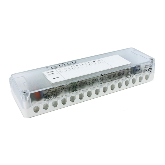
INSTALLATION You are the proud owner of a Delta 8000 technical unit and peripheral elements that make up your complete management system. 1. System presentation Delta 8000 is a heating/cooling management system for hydraulic installations (underfloor or radiators) or for aeraulic installations (ductable). - Page 4 1-> 8 outputs max. Example 3: Room by room regulation, wireless, with centralised programming 30m max. Technical unit Radio/bus gateway Wireless programmer Tydom/Tywell hub 1-> 8 outputs max. BUS 1 BUS 2 Wireless 1-> 8 outputs max. room thermostats 30m max. Example 4: Room by room regulation, hybrid (Bus and wireless), with centralised programming Radio/bus Technical unit...
-
Page 5: Installation Diagrams
In the event that all the parts are controlled, without exception, by the Delta 8000, it is recommended that you install a Bypass. The DELTA 8000 system offers an optional water network temperature monitoring function (hot and cold). This function protects the system from overheating in the water network (protection of the slab and pipes) or from abnormally low temperature, which will generally lead to the formation of condensation on the flooring. -
Page 6: Example Of An Aeraulic Installation Diagram
3.2 Example of an aeraulic installation diagram • 4 zones from wireless thermostats connected to a hub via the Delta 8000 RF gateway DELTA 8000 BT DELTA 8000 RF Technical unit gateway Tydom/Tywell General power supply 230 V~ Damper power supply On/Off control 24 V~/ or 230 V~... -
Page 7: Mounting And Connection
4. Mounting and connection ❶ 4.1 Mounting and connecting the technical unit ❶ Remove the cover and disconnect the electrical supply. ❷ ❷ Mount the unit with a set of screws/sprigs compatible with the substrate (not included). ❸ ❸ Connect the elements (refer to the 'connection' §). Tighten the clamp using the nylon screws supplied to secure the cable. - Page 8 ❷ If your system controls the change-over (heating/cooling mode management), connect the change-over input or output (according to SW6 configuration): OFF Change-over input. From heat pump -> TU ON Change-over output. From TU -> heat pump - If configured as an "input": Delta 8000 automatically toggles from heating to cooling mode and vice versa depending on the information supplied by the heat pump (output available depending on heat pump model) - If configured as an "output": the Delta 8000 technical unit supplies the information regarding the current mode (heating/ cooling) to the heat pump (input available depending on the heat pump model).
-
Page 9: Mounting And Connecting The Delta 8000 Rf Gateway
4.2 Mounting and connecting the Delta 8000 RF gateway ❶ Disconnect the power supply to the technical unit. ❷ ❸ Open the unit door by pushing the pin using a screwdriver. 230V~ 50 Hz 230V~ 230V~ ❹ Attach the base to the support using suitable screws. 50 Hz 50 Hz 230V~... - Page 10 4.3.2 Mounting and connecting the Delta 8000 TA Bus thermostat Mini 20 cm ❶ Disconnect the power supply to the technical unit. ❷ Separate the unit from its base by pushing the pin using a screwdriver. 230V~ 50 Hz ❸ Connect the bus to the terminal block located on the base (no polarity to be respected).
-
Page 11: Overview Of The Lights On The Technical Unit
5. Overview of the lights on the technical unit Pump On/Off LED Status LED Generator On/Off LED Configuration Output LEDs (❽) switches Pump and generator On/ LED status (green) Output LEDs (red) Off LEDs (red) Normal Relay closed On / Activation operation Output on Override mode... -
Page 12: Pairing Of Peripheral Devices To The Delta 8000 Technical Unit
6. Pairing of peripheral devices to the Delta 8000 technical unit 6.1 Pairing of the Delta 8000 RF gateway When switched on, the Delta 8000 RF is automatically recognised by the DELTA 8000 BT. 6.2 Pairing of a Delta 8000 wireless room thermostat ❶... -
Page 13: Pairing Of A Delta 8000 Wireless Programmable Room Thermostat
6.3 Pairing of a Delta 8000 wireless programmable room thermostat ❶ ❶ On the gateway: Press and hold the left-hand button for 3 seconds until LED 1 flashes, then release the button. ❷ ❷ On the thermostat: Turn the dial to ❸... -
Page 14: Pairing Of A Delta 8000 Bus Room Thermostat
6.4 Pairing of a Delta 8000 Bus room thermostat ❶ Press and hold the 1st and 4th buttons for 3 seconds, then release. ❷ The display shows CF20. Press OK, then + and - to select the output or outputs with which the room thermostat will be paired. -
Page 15: Pairing Of A Delta 8000 Bus Programmable Room Thermostat
6.5 Pairing of a Delta 8000 Bus programmable room thermostat >3s ❷ ❸ ❶ Turn the knob to ❶ ❷ Press and hold the 2nd button from the left for 3 seconds. Release the button. ❸ The display shows Ln01. Press OK to open the association mode. -
Page 16: Configuring The Delta 8000 Technical Unit
ON or OFF if terminal 2 is configuration Contact open = Heat mode connected. Lack of sensor or dew point measurement with Delta Dore condensation probe. (In Cooling mode only, the system cuts out in case of condensation). Type of 'water monitoring' ON or OFF measurement. -
Page 17: Configuring The Technical Unit
7.2 Configuring the technical unit From a Delta 8000 room thermostat or programmable room thermostat, it is possible to adjust certain general installation settings. ❶ With a room thermostat (RT) ❶ From the OFF mode, press and hold the 2nd button from the left for 5 seconds. Release the button. ❷... -
Page 18: Advanced Configuration Of The Wireless And Bus Room Thermostat/Programmable Room Thermostat
8. Advanced configuration of the wireless and Bus ❶ room thermostat/programmable room thermostat 8.1 Configuration of the wireless/Bus room thermostat ❶ From Off mode Press and hold the 2nd button from the left for 5 seconds. Release the button. ❷ ❷... -
Page 19: Configuration Of The Wireless/Bus Programmable Room Thermostat
8.2 Configuration of the wireless/Bus programmable room thermostat ❷ ❶ Turn the knob to ❷ Briefly press the OK button. Release the button. ❸ The display shows CF01. ❸ • Press + or - to select the menu. • Press OK to open the setting mode, then + and - to perform the setting. Default configuration Correction of the measured temperature +/- 5°C in 0.1°C increments (0°C by default) -
Page 20: Smart Home Hub / Bioclimatic System Manager Option
9. Smart home hub / bioclimatic system manager option 9.1 Installation of the Tydom/Tywell hub Install your hub in accordance with the information in its instructions. 9.2 Tydom application and pairing ❶ Download the Tydom app. - Log in to either the Google Play or App Store, depending on your device. - Search for and download the free "Tydom"... -
Page 21: Pairing The Room Thermostat With The Tywell Hub
9.3 Pairing the room thermostat with the Tywell hub The Delta 8000 TA wireless thermostat is compatible with the Tywell bioclimatic system manager, meaning it can be recognised as an indoor temperature sensor, as required for the creation of a passive zone (management of blackout blinds for heat protection). -
Page 22: Reset Menus
10. Reset menus You have the ability to reset the various wireless pairings and to restore the factory configuration. ' Advanced ' reset menus are also available and are described in the respective instructions for each product. If you wish to reset your entire system, you must first reset the settings, then the wireless/Bus pairings. 20 s 10.1 Resetting 20 s... -
Page 23: Resetting The Wireless And Bus Pairings
10.1.2 Resetting a Delta 8000 TA wireless/Bus room thermostat This menu restores the system to factory settings, except parameters CF20, CF21 and CF05. ❶ ❶ From OFF mode. Simultaneously press and holed the 1st and 3rd buttons (i) from the left for 10 seconds. The display shows rSt1. - Page 24 10.2.2 Deletion of the wireless pairing of the Delta 8000 TAP thermostat ❷ ❶ Turn the knob to ❶ ❷ Press and hold the 2nd button from the left for 3 seconds. Release the button. The display shows Ln01. >3s ❸...
- Page 25 10.2.5 Deleting all Bus pairings ❶ From a Delta 8000 TA Bus thermostat ❶ From Off mode Press and hold the 2nd button from the left for 5 seconds. Release the button. ❷ ❷ Press and hold the 2nd button from the left again for 3 seconds. Release the button.
- Page 26 10.2.6 Wireless resetting of the Delta 8000 RF gateway Deleting the association of the gateway with a room thermostat ❶ Press and hold the left-hand button for 3 seconds ❶ until LED 1 flashes, then release the button. ❷ ❷ Tap the left-hand button repeatedly to select the channel you want to delete.
-
Page 27: Troubleshooting
11. Troubleshooting 11.1 Technical unit errors When a defect is detected on the system, the symbol flashes on the room unit display. Press 'i' to display the type of defect. After viewing, the symbol is displayed continuously until the problem is fixed. Green LED Bus defect Check connection between the room unit and the technical unit. -
Page 28: Technical Specifications
12. Technical Specifications DELTA 8000 BT Technical unit DELTA 8000 TA RF wireless room thermostat • Main power supply 230 V~/240 V~, +/-10%, 50/60 Hz, • Power supplied by 2 batteries: • Consumption: 2 to 15 VA (5,5W max.) depending on the number of - Alcaline 1.5V, LR03 (AAA) provided, or elements connected to the bus and the number and type of controlled - Lithium 1.5 V, LR03 (AAA), 1200 mAh,... -
Page 29: Use
The Delta 8000 control system enables the management of a hydraulic or aeraulic system, room by room. 1. Wireless and Bus room thermostat 1.1 Description HEAT/COOL button: enables switching from heating to cooling Defect in progress mode and vice-versa, by pressing for 3 seconds Appears in Locked mode Current mode STOP mode, if the thermostat is a 'Master' thermostat and... -
Page 30: Wireless And Bus Programmable Room Thermostats
Locking down settings Press the 'i' button for 5 seconds. symbol appears. Release the button. In this mode: - settings are deactivated, - only the temperature display is authorised. To unlock, press and hold the 'i' button once more for 5 seconds. 2.
Need help?
Do you have a question about the 8000 System and is the answer not in the manual?
Questions and answers