Advertisement
Quick Links
Advertisement

Summary of Contents for FEIERDUN FOR01
- Page 1 SMITH MACHINE FOR01 User Manual...
-
Page 2: Parts List
PARTS LIST Bottom Tube-Right Bottom Tube-Left Side Bottom Tube Bottom Connection Tube Upper Connection Tube Rear Upright Frame-Right Rear Upright Frame-Left Upper Cross Beam Support Frame Weight Support Tube-Right 2PCS 2PCS Weight Support Tube-Left Fixing Bracket Weight Plate Frame Upper Front Connection Tube Front Weight Guide Tube 2PCS 2PCS... - Page 3 PARTS LIST Reserve Tube Lower Bar Handle-Curved Lat Bar Fixed Shaft 20PCS Handle Folded Edge Plate Connect Plate (140mm) Connect Plate (120mm) Trim Panel 2PCS 3PCS 4PCS Pre-installed Pre-installed Special-Shaped Plate Special-Shaped Plate Insert Pin-short Bearing-Big Quick Knob (Circular Hole) 4PCS (Square Hole) 8PCS 2PCS 4PCS...
- Page 4 PARTS LIST Pre-installed Pre-installed Pre-installed 45mm Square End Plug 25mm Round End Plug 50mm Round End Plug 25mm Round End Plug Pulley Bushing-Short 26PCS 4PCS 2PCS 4PCS Pulley Bushing-Long Bolt M12X30mm Bolt M10X85mm Bolt M10X80mm Bolt M10X70mm 4PCS 2PCS 2PCS 3PCS 9PCS Bolt M10X65mm...
- Page 5 ASSEMBLY INSTRUCTIONS STEP 1 1. Attach the Handle (46) to the Bottom Connection Tube (4), using two M10X65mm Carriage Bolts (99), two M10 Washers (103) and two M10 Nylon Nuts (107). 2. Attach the Side Weight Plate Frame (18) to the Side Bottom Tube (3), using two M10X65mm Carriage Bolts (99), two M10 Washers (103) and two M10 Nylon Nuts (107).
- Page 6 ASSEMBLY INSTRUCTIONS STEP 2 1. Attach the two Support Frames (9) to the Bottom Tube (Right & Left) (1&2), using two M10X70 Bolts (90), four M10 Washers (103) and two M10 Nylon Nuts (107). 2. Slide Slide Assembly (19) onto two Support Frames (9). 3.
- Page 7 ASSEMBLY INSTRUCTIONS STEP 3 1. Attach the Weight Support Tube (Right & Left) (10&11) and four Special-Shaped Plates (Circular Hole) (51) to the Bottom Tube (Right & Left) (1&2), using six M10X70mm Carriage Bolts (98), six M10 Washers (103) and six M10 Nylon Nuts (107). 2.
- Page 8 ASSEMBLY INSTRUCTIONS STEP 4 1. Attach the Upper Front Connection Tube (14) and two Connect Plates (140mm) (49) to the two Upper Cross Beams (8), using four M10X70mm Carriage Bolts (98), four M10 Washers (103) and four M10 Nylon Nuts (107). 2.
- Page 9 ASSEMBLY INSTRUCTIONS STEP 5 1. Insert the four Rear Weight Guide Tubes (16) into Bottom Tube (Right & Left) (1&2). 2. In order insert the two Rubber Cushions (73), two Big Washers (20), two Springs (59), two Big Washers (20), one Weight Plate Frame (13) into Rear Weight Guide Tube (16) . 3.
- Page 10 ASSEMBLY INSTRUCTIONS STEP 6 1. Insert the Fixing Bracket (12) into two Rear Weight Guide Tubes (16), using two M10X45mm (93), four Arc Washers (104) and two M10 Nylon Nuts (107). 2. Attach the Fixing Bracket (12) and two Connect Plates (50) to the Weight Support Tube-Right (10) and Upper Cross Beam (8), using four M10X70mm Carriage Bolts (98), four M10 Washers (103) and four M10 Nylon Nuts (107).
- Page 11 ASSEMBLY INSTRUCTIONS STEP 7 1. Insert the two Lever Fixed Tubes (28) into Lever (17). 2. Attach the two Lever Fixed tubes (28) to the two Sliding Tubes (27), using four M10X25mm Bolts (94), eight M10 Washers (103) and four M10 Nylon Nuts (107). 3.
- Page 12 ASSEMBLY INSTRUCTIONS STEP 8 1. Attach the Hook (Right & Left) (36&37), Handle (Right & Left) (34&35), Safety Catch Arm (Right & Left) (32&33) to the two Support Frames (9). 2. Attach the Foam Tube (29) to the Safety Catch Arm-Left (33), using one Insert Pin-long (64).
- Page 13 ASSEMBLY INSTRUCTIONS STEP 9 1. Insert the four Fixed Tubes (23) into Bottom Tube (Right & Left) (1&2) and Safety Catch Arm (Right & Left) (32&33), using four Insert Pins-short (54). 2. Attach the Reserve Tube (41) to the Reverse Bushing (39), using one M10X80mm Bolt (89), two M10 Washers (103) and one M10 Nylon Nut (107).
- Page 14 ASSEMBLY INSTRUCTIONS STEP 10 1. Attach the Trim Panel (48) to the two Upper Cross Beams (8), using two M8X15mm Bolts (97) and two M8 Washers (105). 2. Slide the two ¢50 Barbell Spring Clips (60) into two OB Tubes-Long (38). 3.
- Page 15 ASSEMBLY INSTRUCTIONS NO.6&7 NO.4 NO.3 NO.5 NO.1&2 NO.8 NO.9 -14-...
- Page 16 ASSEMBLY INSTRUCTIONS -15-...
- Page 17 ASSEMBLY INSTRUCTIONS STEP 11 : 1.Start With the Cable (66). a). Install Pulley No.1&2 (67) to Pulley Block (22), using two M10X48mm Bolts (92), four M10 Washers (103) and two M10 Nylon Nuts (107). b). Install Pulley No.3 (67) and two Pulley Bushings (short) (85) to Support Frame (9), using one M10X70mm Bolt (90), two M10 Washers (103) and one M10 Nylon Nut (107).
-
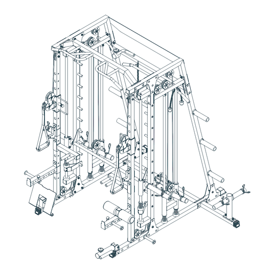
Page 18: Exploded Drawing
EXPLODED DRAWING -17-...
Need help?
Do you have a question about the FOR01 and is the answer not in the manual?
Questions and answers
How to set the timer