Table of Contents
Advertisement
Quick Links
Advertisement
Table of Contents

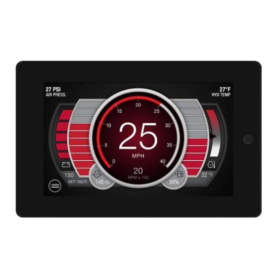
Summary of Contents for Helios ENOVATION CONTROLS PowerVision P70
- Page 1 ® PowerVision Installation Manual 00-02-1230 2023-10-24 Section 78...
- Page 2 To consistently bring you the highest quality, full-featured products, we reserve the right to change our specifications and designs at any time. The latest version of this manual can be found at enovationcontrols.com. BEFORE INSTALLING THIS ENOVATION CONTROLS PRODUCT: Read and follow all installation instructions. Please contact Enovation Controls immediately if you have any questions.
-
Page 3: Table Of Contents
Table of Contents Hardware Installation ......................... 5 Inspecting Package Contents ..................5 Fuse Type / Ratings .....................5 Surface-Mounted Installation ..................6 Ordering Information ....................7 Software Platform ......................7 Pinout Specifications ....................7 Configuration Information ...................... 10 Specifications ........................... 11 Dimensions ..........................13 2023-10-24 00-02-1230... - Page 4 THIS PAGE INTENTIONALLY LEFT BLANK 2023-10-24 00-02-1230...
-
Page 5: Hardware Installation
Hardware Installation ® The following instructions will guide you through installing the PowerVision P70 display. Inspecting Package Contents Before installing the product, it is recommended that you ensure all parts are accounted for and inspect each item for damage (which sometimes occurs during shipping). The items included in the box are: •... -
Page 6: Surface-Mounted Installation
IMPORTANT NOTE: Per IEC 62368-1 requirement the equipment needs to be protected in case of excessive input power. It is recommended that an external fuse be added to the wiring to limit the input power to the device and remove the electrical energy completely in case of a fault. -
Page 7: Ordering Information
Ordering Information The P70 and accessories (if available) can be purchased through Enovation Controls: Part Number Description Order Details Basic PV70 78700712 P70 including internal GPS receiver, 2.4GHz Wi-Fi 78700692 Harness, TBD Software Platform ® PowerVision Configuration Studio 6.x or later Pinout Specifications 23 Position Connector A (Mating Connector AMP 770680-2 Natural) PIN #... - Page 8 Analog Return Ignition CAN 1 L CAN 1 H CAN 2 L CAN 2 H Analog In 1 Analog In 2 Analog In 3 Analog In 4 23 Position Connector B (Mating Connector AMP 770680-5 Blue) PIN # Function Line Out 3 Left P Line Out 3 Left N Digital Out OD 1 Digital Out OD 2...
- Page 9 Analog Out Line Out 1 Left P Line Out 1 Left N Line Out 1 Right P Line Out 1 Right N Line Out 2 Left P Line out 2 Left N Line Out 2 Right P Line Out 2 Right N GPS Antenna (If Equipped) USB Port 2023-10-24...
-
Page 10: Configuration Information
Configuration Information Follow these steps to download a custom configuration to the P70 display: Step Action Turn off the display. Insert the USB drive that contains the new configuration file into the display’s attached USB pigtail. Place a magnet onto the area shown here on the upper middle side of the back of the display: Power the display back on, continually holding the magnet in place. -
Page 11: Specifications
Step Action Touch the up or down arrow keys on the screen until the appropriate configuration file from the USB to be loaded into the display is shown on the screen. Press the right arrow/green arrow key on the screen twice to load the selected configuration. - Page 12 Hardware Li-Ion battery backup (Typ. Lifespan minimum 10 years), non-rechargeable, non- Real-time Clock: replaceable (1) Ampseal 23 pin (1) Ampseal 23 pin Connectors: (1) USB Bulkhead (1) GPS Fakra Antenna Jack (Optional) Video Inputs: (2) NTSC/PAL (Single channel viewable, Differential) Communication (2) CAN 2.0B according to ISO 11898-2;...
-
Page 13: Dimensions
Infotainment (Optional (2) Outputs (Stereo, 20Hz-20kHz, Differential) Stereo (1) Subwoofer (mono, configurable, 30Hz-250Hz) (1) Amp Turn On/Accessory USB Media MP3, MP4 Playback Bluetooth Audio Streaming; Fully integrated Bluetooth 5.0 Class 1 (P/N 78700692) Dimensions 2023-10-24 00-02-1230... - Page 14 2023-10-24 00-02-1230...
- Page 15 THIS PAGE INTENTIONALLY LEFT BLANK 2023-10-24 00-02-1230...

Need help?
Do you have a question about the ENOVATION CONTROLS PowerVision P70 and is the answer not in the manual?
Questions and answers