Table of Contents
Advertisement
Quick Links
Board Manual
Secure Gateway-V1.1
For AURIX™ family
About this document
Scope and purpose
This document describes the features and hardware details of the Secure Gateway-V1.0 and V1.1 equipped with
an TriCore AURIX™ Microcontroller from Infineon Technologies AG.
Intended audience
This document is intended for anyone who wants to develop software on the Secure Gateway-V1.0 and V1.1 or
wants to use this kit for evaluating and demonstrating the capabilities of the AURIX™ microcontroller in
combination with other Infineon Technologies products.
Table of contents
About this document ....................................................................................................................... 1
Table of contents ............................................................................................................................ 1
1
Introduction of the Secure Gateway V1.1 .......................................................................... 3
1.1
Key features ............................................................................................................................................. 3
1.2
Block diagram .......................................................................................................................................... 4
2
Hardware description .................................................................................................... 5
2.1
Power supply ........................................................................................................................................... 6
2.1.1
TLF30682QVS01 .................................................................................................................................. 6
2.1.2
Power supply sequencing and power down ..................................................................................... 8
2.1.3
Supply Monitoring functions ............................................................................................................. 9
2.2
Gateway Board Resets .......................................................................................................................... 10
2.3
AURIX™ 2G CPU to Switch connections ................................................................................................ 11
2.4
AURIX™ 2G CPU to PHY connections ..................................................................................................... 12
2.5
AURIX™ Ethernet MAC Address EEPROM .............................................................................................. 13
2.6
MDI Address configuration .................................................................................................................... 13
2.7
TC377TX Ethernet PPS signal ................................................................................................................ 14
2.8
Marvell Ethernet Components .............................................................................................................. 14
2.8.1
1000/100Base-T1 CMC and PoDL ..................................................................................................... 14
2.8.2
Standard 1000Base-T1 / 100Base-T1 connector ............................................................................. 15
2.8.3
Standard 1000Base-T1 / 100Base-T1 quad-connector ................................................................... 15
2.8.4
1000Base-TX Magnetics and RJ45 Jack ........................................................................................... 16
2.9
Molex Mini50 CAN-FD ............................................................................................................................ 16
2.9.1
CAN-FD Signals on Molex connectors .............................................................................................. 17
2.10
Molex Mini50 FlexRay™ LIN PSI5S ......................................................................................................... 18
2.10.1
FlexRay™ ........................................................................................................................................... 19
2.10.2
LIN ..................................................................................................................................................... 19
2.11
QSPI channels ........................................................................................................................................ 20
2.12
eMMC NAND flash memory ................................................................................................................... 21
2.13
General Purpose LEDs ........................................................................................................................... 21
2.14
Extension Header X1109 ....................................................................................................................... 22
User's Manual
R1.2
2020-11-16
Advertisement
Table of Contents

Related Manuals for Infineon Secure Gateway-V1.1

Summary of Contents for Infineon Secure Gateway-V1.1
-
Page 1: Table Of Contents
Scope and purpose This document describes the features and hardware details of the Secure Gateway-V1.0 and V1.1 equipped with an TriCore AURIX™ Microcontroller from Infineon Technologies AG. Intended audience This document is intended for anyone who wants to develop software on the Secure Gateway-V1.0 and V1.1 or wants to use this kit for evaluating and demonstrating the capabilities of the AURIX™... - Page 2 Secure Gateway-V1.1 For AURIX™ family Software initialization sequence ..................23 Schematic and PCB ....................... 24 Appendix A ........................25 Revision history..........................26 User's Manual R1.2 2020-11-16...
-
Page 3: Introduction Of The Secure Gateway V1.1
Introduction of the Secure Gateway V1.1 Introduction of the Secure Gateway V1.1 The Secure Gateway-V1.1 offers a huge range of Application use cases. With the AURIX™ TC377TX in combination with Marvell’s 88Q5050 Switch and 88Q2112 1000Base-T1 PHY future In Vehicle Networks can be addressed and evaluated. -
Page 4: Block Diagram
Secure Gateway-V1.1 For AURIX™ family Introduction of the Secure Gateway V1.1 Block diagram The block diagram in Figure 1 shows the main components of the Secure Gateway-V1.1 and interconnects between the used devices. Figure 1 Block diagram of the Gateway Board User's Manual R1.2... -
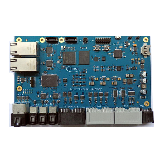
Page 5: Hardware Description
Secure Gateway-V1.1 For AURIX™ family Hardware description Hardware description The following chapters provide a detailed description of the hardware and how it can be used. Figure 2 PCB of the Secure Gateway-V1.1 User's Manual R1.2 2020-11-16... -
Page 6: Power Supply
Power supply The Power Supply concept must guarantee a stable supply of the Board. The standard Input voltage is 12V. Out of several voltages will be generated. Figure 3 visualize the power domains and used structure of Infineon’s supply IC behind. - Page 7 Secure Gateway-V1.1 For AURIX™ family Hardware description provides the 5V-domain for transceiver. Integrated switches, compensation and the high switching frequency is both minimizing the number and the value of external components required. Additional features are under-/over-voltage monitoring (via independent reference) of all integrated and up to two external rails as well as a flexible watchdog concept to supervise the µC offers high flexibility for multiple...
-
Page 8: Power Supply Sequencing And Power Down
Secure Gateway-V1.1 For AURIX™ family Hardware description QSPI4 MRST P22.1 /ESR1 Reset /PORST /PORST P40.6 2.1.2 Power supply sequencing and power down The Secure Gateway-V1.1supply is converted into several different voltage domains. Powering up the board will switch on the cascaded voltage ICs. -
Page 9: Supply Monitoring Functions
Secure Gateway-V1.1 For AURIX™ family Hardware description 2.1.3 Supply Monitoring functions The Secure Gateway-V1.1provide several monitoring functions to determine the correct voltage levels, acting according violations and provide these as meta data to higher management functions. The following tables list the signals connected to the VADC of TC377TX. -
Page 10: Gateway Board Resets
Secure Gateway-V1.1 For AURIX™ family Hardware description Gateway Board Resets The Secure Gateway-V1.1features several reset sources and groups depending on connected devices. The TC377TX reset source is the /PORST signal driven by the TLF30682QV01. The reset of Marvell’s Ethernet components is generated out of power good signals coming from the DC/DC converters and the TC377TX Pin P21.1. -
Page 11: Aurix™ 2G Cpu To Switch Connections
Secure Gateway-V1.1 For AURIX™ family Hardware description AURIX™ 2G CPU to Switch connections The AURIX™ TC377TX provides two 1Gbit Ethernet MAC’s using RGMII to connect a Switch or PHY. On the Secure Gateway-V1.1the AURIX™ device is connected via GMAC0 RGMII interface to Marvell’s 88Q5050 switch on Port 8. -
Page 12: Aurix™ 2G Cpu To Phy Connections
Secure Gateway-V1.1 For AURIX™ family Hardware description Table 3 shows the signal connection list for the connection between CPU and the Ethernet Switch. Table 3 Connection between TC377TX and the Ethernet Switch Module Signal Comment GMAC TXD0_0 P11.3 GETH_TXD0 GMAC TXD1_0 P11.2... -
Page 13: Aurix™ Ethernet Mac Address Eeprom
Secure Gateway-V1.1 For AURIX™ family Hardware description AURIX™ Ethernet MAC Address EEPROM The Secure Gateway-V1.1supports an I2C EEPROM and a Real-Time-Clock (RTC) with two a unique MAC address. Software can load these and use it to configure the Ethernet GMAC’s. -
Page 14: Tc377Tx Ethernet Pps Signal
Secure Gateway-V1.1 For AURIX™ family Hardware description TC377TX Ethernet PPS signal Both Ethernet MAC provide a PPS signal which can be selected on a GPIO. For GMAC the GPIO pin used is P14.4. For GMAC1 the GPIO pin used is P21.0. Both signals are available on a pin header. -
Page 15: Standard 1000Base-T1 / 100Base-T1 Connector
Secure Gateway-V1.1 For AURIX™ family Hardware description 2.8.2 Standard 1000Base-T1 / 100Base-T1 connector Rosenberger H-MTD® is a 360° fully shielded differential connector system. The new developed system combines high-performance data transmission up to 15 GHz or 20 Gbps and a small package size in a robust automotive grade housing. -
Page 16: 1000Base-Tx Magnetics And Rj45 Jack
Secure Gateway-V1.1 For AURIX™ family Hardware description 2.8.4 1000Base-TX Magnetics and RJ45 Jack To connect the Secure Gateway-V1.1to a standard IT infrastructure two RJ45 jacks for voltage driven PHYs provide CAT6/CAT7 cables connections. One Gbit Ethernet port is connected as port 6 to the 88Q5050 Switch, the second is connected to AURIX GMAC1 over the 88EA1512 Marvell PHY. -
Page 17: Can-Fd Signals On Molex Connectors
Hardware description 2.9.1 CAN-FD Signals on Molex connectors In sum the Secure Gateway-V1.1provides 12 CAN-FD channel with different Infineon CAN transceivers like the TLE9250, TLE9252, TLE9254, TLE9255 allowing exercising partial Network capabilities. This connectors are colored gray on that board. -
Page 18: Molex Mini50 Flexray™ Lin Psi5S
Secure Gateway-V1.1 For AURIX™ family Hardware description CAN1 CAN12_RXDB P10.8 X1107.22 CAN_H CAN 1 Node 2 CAN1 CAN12_TXD P10.7 X1107.21 CAN_L CAN 1 Node 2 CAN2 CAN23_RXDA P14.9 X1107.7 CAN_H CAN 0 Node 3/ CAN 2 Node 1 CAN2 CAN23_TXD P14.10... -
Page 19: Flexray
Zero Ohm R263 resistor (assembled) ERRN P40.3 P15.8 2.10.2 There are 2 LIN channels available on the Molex connector X1105 of the Secure Gateway-V1.1 using Infineon’s TLE7258. Table 11 shows the LIN signal connection list. Table 11 LIN Signal List... -
Page 20: Qspi Channels
2.11 QSPI channels There are 4 QSPI channels available on the Secure Gateway-V1.1. Using various chip select lines allow addressing for several slave ICs like the PMIC device TLF30682QVS01, as well as CAN and Flexray transceivers. Table 12 shows the QSPI signal connection list. -
Page 21: Emmc Nand Flash Memory
Secure Gateway-V1.1 For AURIX™ family Hardware description 2.12 eMMC NAND flash memory For Data storage like for example Firmware images an eMMC NAND flash memory of 4GB is on the Secure Gateway-V1.1This eMMC is connected to AURIX™ SDMMC module. Typically eMMC devices from ISSI are used. -
Page 22: Extension Header X1109
Secure Gateway-V1.1 For AURIX™ family Hardware description 2.14 Extension Header X1109 Next to the two RJ45 Connectors a signal extension Header is available for extending use case of the Secure Gateway-V1.1. Beside the HSSL interface, a QSPI with two chip select signals and one I2C channel a SGMII 1Gb/s interface is available. - Page 23 Software initialization sequence Software initialization sequence For example projects please refer to Infineon MyCIP system. There you will find software examples for the AURIX™ TC377TX. Marvell Ethernet components shell boot up automatic by its own. In the AURIX™ only basic support for these components is given in form of binary libraries.
- Page 24 For AURIX™ family Schematic and PCB Schematic and PCB The schematic and layout data can be requested by Infineon as long the user has a valid NDA with Marvell. Please contact either Infineon or Marvell contacts for that. User's Manual R1.2...
-
Page 25: Www.infineon.com
Secure Gateway-V1.1 For AURIX™ family Appendix A Appendix A For future information about the Infineon products, Marvell IC’s, ISSI eMMC and Rosenberger connectors please contact the companies below. Infineon Technologies AG Marvell Rosenberger Rosenberger Infineon Technologies AG Marvell Semiconductor, Inc. - Hochfrequenztechnik GmbH &... - Page 26 Secure Gateway-V1.1 For AURIX™ family Appendix A Revision history Major changes from V1.0 to V1.1 of the manual Page or reference Description of change Correct Table for Ethernet MAC connections in chapter Add Current measurement channel into the table Major changes from V1.1 to V1.2 of the manual...
- Page 27 For information on the types © 2020 Infineon Technologies AG. any and all warranties and liabilities of any kind Board Manualowners. in question please contact your nearest Infineon All Rights Reserved. (including without limitation warranties of non- Technologies office.
Need help?
Do you have a question about the Secure Gateway-V1.1 and is the answer not in the manual?
Questions and answers