Table of Contents
Advertisement
Quick Links
Advertisement
Table of Contents

Summary of Contents for TELEDYNE OLDHAM SIMTRONICS Everywhereyoulook CPS CPS 10 SYSTEM
- Page 1 USER MANUAL CPS_CPS 10 SYSTEM NPCPSGB-Revision K.0...
- Page 2 User Manuals in other languages are available on Website https://teledynegasandflamedetection.com Copyright December 2023 by TELEDYNE OLDHAM SIMTRONICS S.A.S. All rights reserved. Reproduction in any form, in whole or in part, without the express written consent of TELEDYNE OLDHAM SIMTRONICS S.A.S. is strictly prohibited.
- Page 3 • TELEDYNE OLDHAM SIMTRONICS neither supports nor authorises any company, physical or moral person to assume responsibility on behalf of TELEDYNE OLDHAM SIMTRONICS , even if it is involved in the sale of TELEDYNE OLDHAM SIMTRONICS products. •...
- Page 4 Although every effort is made to ensure accuracy, this manual may contain unintentional technical inaccuracies. TELEDYNE OLDHAM SIMTRONICS reserves the right to modify the technical characteristics of its equipment without notice to improve product performance on behalf of its clients.
- Page 5 • halogenated compounds (R134a, HFO, etc.). • organo-phosphorus compounds (e.g. herbicides, insecticides, and phosphate esters in fireproof hydraulic fluids. TELEDYNE OLDHAM SIMTRONICS recommends regular testing of fixed gas detection installations (read 6.4). The installation of this product and all electrical connections should be performed by a qualified professional, in accordance with the manufacturer’s specifications...
- Page 6 CPS_CPS 10 SYSTEM USER MANUAL NPCPSGB Revision K.0...
-
Page 7: Table Of Contents
CPS_CPS 10 SYSTEM USER MANUAL Table of Contents Overview of the CPS System ............1 The CPS central controller ................3 Digital addressable modules ................ 4 Digital linking ....................... 4 The COM_CPS software application ............6 Architecture du système ................7 Assembly / Installation .............. - Page 8 CPS_CPS 10 SYSTEM USER MANUAL Control Menu ....................... 39 Acces code ......................43 System Menu ....................... 43 Maintenance Menu ..................46 Maintenance ................... 53 Program transfer ....................53 Error messages ....................54 Checksum error ....................55 Testing and calibration of fixed installations ........... 56 Central controller maintenance ..............
-
Page 9: Overview Of The Cps System
CPS_CPS 10 SYSTEM USER MANUAL Overview of the CPS System The CPS (CAR PARK SYSTEM) system is designed to measure and monitor pollutants in underground parking facilities and tunnels. The system consists of: • a central controller for collecting readings and managing alarms; •... - Page 10 CPS_CPS 10 SYSTEM USER MANUAL Example of application « parking « NPCPSGB Revision K.0...
-
Page 11: The Cps Central Controller
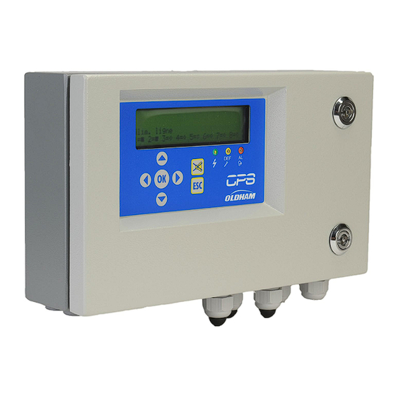
CPS_CPS 10 SYSTEM USER MANUAL The CPS central controller Figure 1: CPS The central controller is available in a wall-mount version. It is designed to control: • 256 digital modules distributed over 8 lines, with a maximum of 32 modules per line; •... -
Page 12: Digital Addressable Modules
0.22 mm² in diameter. One pair supplies power to the module, the second pair is used for the digital RS-485 link. TELEDYNE OLDHAM Simtronics – personnel should verify that the correct cable has been used in terms of type and capacity. - Page 13 CPS_CPS 10 SYSTEM USER MANUAL Figure 2 CABINET Relay Logic input Sorties analogiques CPS RM8 CPS AI16 CPS AO4 Module 1 32 MODULES NUMERIQUES PAR LIGNE MAXIMUM Module 2 Module 3 Max length line: 1.2 Km (up to 4.8km with repeaters optional.) Module n Module n Module n...
-
Page 14: The Com_Cps Software Application
CPS_CPS 10 SYSTEM USER MANUAL _CPS software application _CPS software application is designed to help configure the CPS central measuring controller on a PC. _CPS software operations are addressed in a separate manual. 1.4.1 System and Hardware Requirements: _CPS must be installed on a PC running Windows 2000 or Windows XP. The minimum requirements to install _CPS are: •... -
Page 15: Architecture Du Système
CPS_CPS 10 SYSTEM USER MANUAL Architecture du système Figure 3 NPCPSGB Revision K.0... - Page 16 CPS_CPS 10 SYSTEM USER MANUAL NPCPSGB Revision K.0...
-
Page 17: Assembly / Installation
CPS_CPS 10 SYSTEM USER MANUAL Assembly / Installation Installation of the CPS central controller The CPS central controller should be installed in a dry, climate-controlled area protected from explosive gases and dust. Ideally, the station should be located in a secure, accessible location under surveillance (security office, control room, equipment room ...). -
Page 18: Connection Of Modules In A Line
CPS_CPS 10 SYSTEM USER MANUAL 2.2.2 Mounting the other modules The other modules (relay, logic input, analog output) should be mounted on a DIN rail inside of a cabinet or an electric box (Figure 2). DIN Rail Figure 5: Detector module OLCT 10N Figure 6: Addressable digital module Connection of modules in a line All modules in a line should be wired in-line from the controller, not in a hub and... -
Page 19: The Cps Central Measuring Controller
CPS_CPS 10 SYSTEM USER MANUAL The CPS Central Measuring Controller View of wall-mounted CPS Figure 7 PART DESIGNATION PART NUMBER Wall casing 6514868 Front panel 6122477 Battery pack (optional) 6311098 Mother board 6451596 24V 60W Power supply 6111308 MX 256 Controller display 6314610 RS232 SUB D9 Connector... -
Page 20: Overview Of The Motherboard
CPS_CPS 10 SYSTEM USER MANUAL Overview of the Motherboard Figure 8 Part Connector function 24 VDC external power supply connection 110-240VCA power supply for (wall-mount) power supply module 24 VDC power supply output for power supply module motherboard power Internal contact relay outputs (RTC) dry contacts, potential free Digital addressable modules 8 line connectors for connecting digital modules (CPS 10 –... -
Page 21: Central Controller Electrical Connections
CPS_CPS 10 SYSTEM USER MANUAL Part Connector function Front Panel connector Display connector Battery Pack (optional) R1, R2, R3: controller shared internal relays Central controller electrical connections Electrical connections are wired through the central controller MOTHERBOARD and the power supply 24V. For the CPS central controller (wall-mounted version), you must open the casing door to access the electrical panel. - Page 22 CPS_CPS 10 SYSTEM USER MANUAL 3.3.3 Digital lines The various digital modules are connected with “Bus” connectors (Fig. 5). Recommended cable: RS-485: 2 shielded twisted pairs, 100 Ω. One pair is used to power the module, and the other is used for communication. The cable shield or tress should be connected to the terminal: Data wires and the schield wires should be cut as short as possible.
- Page 23 CPS_CPS 10 SYSTEM USER MANUAL 3.3.5 RS-485 serial link out Recommended cable: RS-485 cable: 1 shielded twisted pair, 100 Ω. Figure 9 NPCPSGB Revision K.0...
- Page 24 CPS_CPS 10 SYSTEM USER MANUAL 3.3.6 Inspecting the digital buses Bicolor (red/green) LEDs located above each line start, on the motherboard, allows for inspection of the bus links as follows : LED appearance Status Red + Green LEDs lit (LEDs Communication DEL of the bus Normal operation.
- Page 25 CPS_CPS 10 SYSTEM USER MANUAL The buzzer’s pitch will vary according to the alarm threshold. Alarms 1 and 2 have the same frequency. Alarms 3 and 4 have a different pitch, allowing the operator to distinguish between alarm levels. The buzzer can be disconnected by removing the “buzzer activation strap” (J10) located on the motherboard next to the buzzer (cf -: Overview of the Motherboard).
- Page 26 CPS_CPS 10 SYSTEM USER MANUAL Figure 12 USB Interface (Rep 1,Figure 12) Use a USB cable to connect the PC to the CPS central controller running the _CPS application. The USB interface emulates a serial port and is preferable to an RS-232 serial connection. The corresponding USB driver must be installed before the PC is connected to the central measuring station (see _CPS instructions).
-
Page 27: The Front Panel Circuit
CPS_CPS 10 SYSTEM USER MANUAL 3.3.10 RS-485 serial connection The RS-485 serial port (3) is reserved for the supervision system and is composed of an RS-485 interface using JBUS/MODBUS protocol. A table containing all of the important information pertaining to the central controller can be found in the corresponding annex of Chapter 8. - Page 28 CPS_CPS 10 SYSTEM USER MANUAL Display Screen Keys Key used to acknowledge a locked SOLID = instantaneous alarm 3 alarm (programmed for manual acknowledgement) or to dismiss a BLINKING = averaged alarm 3 (takes buzzer relay after its holding time, priority over solid state) even if an alarm is still active.
-
Page 29: Com
CPS_CPS 10 SYSTEM USER MANUAL Alarm thresholds _CPS Six alarm thresholds can be programmed and adjusted for each sensor: Alarm 1, Alarm 2, Alarm 3, Alarm 4, Out of Range and Fault. Alarms 1 – 4 can be: • Instantaneous; •... -
Page 30: Com_Cps Alarm Acknowledgement
CPS_CPS 10 SYSTEM USER MANUAL Alarm acknowledgement COM_CPS Alarms can be rearmed in two ways: Manual acknowledgement: the audible alarm can only be dismissed after the “Acknowledge” button on the CPS central measuring controller has been pushed; Automatic acknowledgement: the audible alarm will be automatically dismissed once the alarm condition has ended. -
Page 31: Digital Modules
CPS_CPS 10 SYSTEM USER MANUAL Digital Modules View of Digital Modules 4.1.1 SENSOR MODULE CPS 10 Part DESIGNATION EXPLO CPS 10 SENSOR MODULE 6 513 591 6 513 592 6 513 593 6 513 594 CPS 10 SENSOR 6 798 301 6 113 331 6 113 332 CPS 10 BOARD... - Page 32 CPS_CPS 10 SYSTEM USER MANUAL 4.1.2 RELAY MODULES CPSRM4-CPSRM8 Figure 14 Designation CPS RM4 CPS RM8 6313962 6313963 Designation Power supply & network connector Programmable relays ( 8 or 4 ) potential free RTC output contact Safety switch + or - relays Configuration switches (Adresses) Logic Input terminals (2 Inputs) 4.1.3...
-
Page 33: Connecting Digital Modules
CPS_CPS 10 SYSTEM USER MANUAL 4.1.4 ANALOG OUTPUT MODULE Figure 16 Designation 4 analog output module 6313980 Part Designation Power supply & network connector Analog output terminal (4 outputs) Configuration switches (Adresses) Module board Logic Input terminals (2 Inputs) Connecting Digital Modules 4.2.1 General topology of the RS-485 network Modules are connected in “parallel”... - Page 34 CPS_CPS 10 SYSTEM USER MANUAL 4.2.2 Wiring the digital network An improper installation can cause incorrect gas level readings or system failure. Do not run cable near equipment such as motors, transformers, or any lines generating a large magnetic field. Always check to ensure that the cables are completely separated from other circuits.
-
Page 35: Configuring The Communication Settings
CPS_CPS 10 SYSTEM USER MANUAL Configuring the communication settings 4.3.1 Slave address All modules in a line should be identified with a unique slave number. Switches 1-5 on the Configuration Switches unit ( ) contained in each module, Figure 19 allow you to set a binary numerical address (1…32).. -
Page 36: Cps 10 Detector Module
CPS_CPS 10 SYSTEM USER MANUAL 4.3.2 End of line resistor The last module in each line should be equipped with an end of line resistor.To connect the resistor, flip the number 8 configuration switch (EOL RESISTOR) of the last module into the ON position. -
Page 37: External Relay Module
CPS_CPS 10 SYSTEM USER MANUAL • The name of the gas: Carbon monoxide, Nitric oxide, Oxygen, Methane … • Unit: ppm, LEL, %v/v … • Range with display format: 100, 10.0, 1.00, … • Actionable thresholds: - 4 instantaneous thresholds: 0-100% measuring range, - 4 averaged thresholds: 0-100% measuring... - Page 38 CPS_CPS 10 SYSTEM USER MANUAL Each of the 6 sensor alarms [AL1 - AL2 - AL3 - AL4 - Out of Range - Fault] can control one or more of the 256 relays. Several events can be linked to one relay. In case of a module relay fault, all relays of this module are restarted.
- Page 39 CPS_CPS 10 SYSTEM USER MANUAL 4.5.3 Configuration des relais _CPS “Normal” relays The relay is activated when an alarm occurs and is deactivated when the alarm condition ends. The variables acting on a relay in alarm status are: • Alarm delay •...
- Page 40 CPS_CPS 10 SYSTEM USER MANUAL The working logic of the relays defined hereafter, takes into consideration the start-up and shut- down intervals during which very high levels of current may occur, capable of damaging motor windings if phases occur in the incorrect sequence. “LS / HS”...
-
Page 41: Com
CPS_CPS 10 SYSTEM USER MANUAL Default Phases Action operation Delay* LS-HS stop delay Duration, in seconds, after low or high 10 min. speed ventilator operation has been Adjustment(s): [ 1 … 32767 ] stopped, before the ventilator can be restarted at low speed. Time values can be modified. - Page 42 CPS_CPS 10 SYSTEM USER MANUAL • Supervision remote screen Input • Priority logic Input • Logic Input • Control from the control unit keypad or forcing relays via supervision • Module alarm / fault Fig u re 22: Lo g ic In p u t Mo d u le Analog Outputs Module COM_CPS This module is comprised of 4 opto-isolated 4-20 mA analog outputs which can be individually...
- Page 43 CPS_CPS 10 SYSTEM USER MANUAL An analog output ON command from the central controller corresponds to 20 mA. Example of use with analog output module Figure 23 : Analog output module NPCPSGB Revision K.0...
- Page 44 CPS_CPS 10 SYSTEM USER MANUAL NPCPSGB Revision K.0...
-
Page 45: Detailed Menus
CPS_CPS 10 SYSTEM USER MANUAL Detailed Menus Menu Tree Start Display Events Cycle Starting If a button is not pushed during 10 min, the display mode, determined by fault in the menu < System > < Start Config > is automatically used Scan&... -
Page 46: Start-Up Phase
CPS_CPS 10 SYSTEM USER MANUAL Start-up Phase No faults or alarms are processed during the first minute after start-up. During this phase, the controller runs a Checksum test (1), a RAM test (2), a line start-up (3) and a module mapping test with a program stored in its memory Voltage builds progressively in the lines. -
Page 47: Control Menu
CPS_CPS 10 SYSTEM USER MANUAL In case of a power outage, the program configuration will be saved. When the controller is COM256 turned on, the last program installed by will be loaded. If a sensor faults, the message “Def” will replace the reading value. - Page 48 CPS_CPS 10 SYSTEM USER MANUAL 5.3.2 Sensor Display This menu allows you to freeze the display on a specific sensor by selecting the line and the module number (The program automatically selects active sensor modules). Touching the [ OK ] key once will bring up the sensor name, the abbreviated gas name, the gas level and unit of measure (ppm, % LEL, $v/v).
- Page 49 CPS_CPS 10 SYSTEM USER MANUAL Alarm 2 triggered 30/06/06 14:49:37 L:8, Mod:02 OFF ⇒ ON Alarm 2, State change for Relay 2 (command relay) 30/06/06 14:49:37 L :8, Mod:29 Relay 2 Normal ON Conditions for Alarm 2 end 30/06/06 14:51:03 L:8, Mod:02 ON ⇒...
- Page 50 CPS_CPS 10 SYSTEM USER MANUAL 5.3.6 Printing “System status” Report This menu is used to initiate the printing of system status reports. The second part indicates the fault status for all of the modules in each line. Each hexadecimal number corresponds to a module, with Module 1 being on the left, and Module 32 on the right.
-
Page 51: Acces Code
CPS_CPS 10 SYSTEM USER MANUAL Calibration 1 Capteur 4 01 CO Xo1 = 00004 Zero value before starting procedure Xo2 = 00000 Zero value Xo3 = 00000 Zero value after procedure Xf1 = 00095 Value of the concentration of calibration gas Xf2 = 00100 Value of the response to the gas Xf3 = 00100 Value of the reading at the end of the procedure Acces code... - Page 52 CPS_CPS 10 SYSTEM USER MANUAL A thermal fuse protects the line’s power supply from short-circuits. Should a short-circuit occur, a fault word will appear in the menu and an error message will be recorded in the event log. After the short-circuit, the line must be reactivated via the menu.
- Page 53 CPS_CPS 10 SYSTEM USER MANUAL 5.5.4 Date and Time Changing the time settings will reinitialize LS and HS delays ! Example : If the HS relay is activated and the time is changed, the HS relay will stop so that the LS relay can operate according to the predetermined delays.
-
Page 54: Maintenance Menu
CPS_CPS 10 SYSTEM USER MANUAL Maintenance Menu 5.6.1 Simulation This menu is used to simulate the alarms for a particular sensor module or to temporarily activate one or more relays (or outputs). After exiting the simulation menu, the sensors and relays (excluding LS and HS relays) revert to their prior state. - Page 55 CPS_CPS 10 SYSTEM USER MANUAL (can only be shut down by a logic input) After exiting this menu, the relay will revert to its original state. Analog Output Simulation 5.6.2 Module Verification Inspection of all of the parameters relating to a communication fault module with a E = Status word...
- Page 56 CPS_CPS 10 SYSTEM USER MANUAL (a) : represents successful transmission attempts. This number increases continually and should be as large as possible. (b), (c), (d) : represents next 3 successive retransmission attempts, if necessary, following a failed attempt. In the event that the 1 attempt (1) fails, a 2 attempt (b) will occur, then a 3...
- Page 57 CPS_CPS 10 SYSTEM USER MANUAL Status word 1 = BitEtatLiss 1 = BitEtatChg 1 = BitEtat0 1 = BitMod0 2 = BitJbFill 2 = BitEtatPar 2 = BitEtat1 2 = BitMod1 4 = BitJbDelay 4 = BitJbWait 4 = BitEtat2 4 = BitMod2 8 = BitEtatCell ** 8 = BitJbCar...
- Page 58 Line : 1 Module : 2 = module recognition error Line : 1 Module : 3 = communication error 5.6.4 Reset maintenance Reserved for TELEDYNE OLDHAM SIMTRONICS - maintenance personnel only. COMCPS Version – Available memory level Displays the controller version as well as the COMCPS programming software version.
- Page 59 CPS_CPS 10 SYSTEM USER MANUAL Exceeding the scale Each sensor logs the amount of time that levels exceed the scale in seconds. Go to the “Module Verification” menu to see this time. NPCPSGB Revision K.0...
- Page 60 CPS_CPS 10 SYSTEM USER MANUAL NPCPSGB Revision K.0...
-
Page 61: Maintenance
CPS_CPS 10 SYSTEM USER MANUAL Maintenance Program transfer This chapter describes the transfer of data from the _CPS application to the CPS, and vice versa (see the _CPS user’s guide). After launching the software, you will see a welcome window. 6.1.1 PC ... -
Page 62: Error Messages
CPS_CPS 10 SYSTEM USER MANUAL 6.1.2 CPS PC transfer Step 1: establish a connection 1) Use either the USB or RS-232 adapter to connect the PC to the CPS central controller. 2) Ensure that the CPS central measuring controller is connected to a power source. 3) On the central controller: flip the programming switch to the “MEM”... -
Page 63: Checksum Error
CPS_CPS 10 SYSTEM USER MANUAL Checksum error When the central controller starts up, checksum values appear briefly on screen after the display test. The value calculated by the central controller is displayed on the first line, and the checksum calculated by the PC with the _CPS software is displayed on the 2nd line. -
Page 64: Testing And Calibration Of Fixed Installations
CPS_CPS 10 SYSTEM USER MANUAL Testing and calibration of fixed installations Warning : The setting of this section are reserved for authorized persons formed because they might call into question the reliability of detection. The site responsible is required to establish security procedures on its site. TELEDYNE OLDHAM SIMTRONICS may be not responsible for their implementation. - Page 65 CPS_CPS 10 SYSTEM USER MANUAL 6.4.2 Semi-automatic calibration During a sensor module calibration, the central controller blocks the alarms from the module in question and displays a maintenance key on the screen. Up to 10 sensors can be calibrated at the same time.
- Page 66 USER MANUAL 6.4.3 Manual calibration The calibration kit provided by TELEDYNE OLDHAM Simtronics must be used (Ref. 6 116 291) female connector / wires / voltmeter connection files). • Remove the sensor cover. • Connect the cable (strand) to the circuit’s male connector.
- Page 67 CPS_CPS 10 SYSTEM USER MANUAL 6.4.4 Semi-automatic calibration device Calibration LED Magnet position Respect the magnet position in order to place the magnet Semi-automatic calibration The magnetic calibration allows for one-man and non- intrusive calibration to save considerable time. Manual calibration with zero and span potentiometers is possible by opening the CPS 10 Slug the gas with a Calibration element...
-
Page 68: Central Controller Maintenance
CPS_CPS 10 SYSTEM USER MANUAL Central controller maintenance Do not use alcohol- or ammonia-based liquids to clean the central controller. If necessary, clean the exterior of the central controller with a damp cloth. 6.5.1 Lithium battery If the central controller configuration settings are lost, the lithium battery soldered to the display card must be replaced. -
Page 69: Technical Specifications
CPS_CPS 10 SYSTEM USER MANUAL Technical Specifications CPS Central Controller CPS w/ metal wall-mounted casing Dimensions (mm) : 320 * 180 * 95 Degree of protection: IP 54 Cable entries 5 M20 cable glands Diameter 5-12 mm power / local relays. -
Page 70: Cps 10 Sensor Module
CPS_CPS 10 SYSTEM USER MANUAL Keyboard Membrane keyboard, 7 intuitive keys Local buzzer Alarm and fault signaling Integrated printer Optional for rack version (no integrated printer option for the metallic wall casing) Alarms 6 alarms per sensor (AL1, AL2, AL3, AL4, Out of Number of alarms: Range, Fault + Validation for Explo gas) Programmable thresholds:... -
Page 71: Cps Rm4 Or Rm8 Relay Module
CPS_CPS 10 SYSTEM USER MANUAL Calibration: Automatic, no need to open the sensor due to a gas introduction device equipped with a magnetic switch, or with a potentiometer inside of the case. Sensor replacement: Sensor replacement switch on the interior of the CPS 10 case. Detection of sensor CPS RM4 or RM8 Relay Module Dimensions (mm):... -
Page 72: Cps Di16 Logic Inputs Module
CPS_CPS 10 SYSTEM USER MANUAL CPS DI16 Logic Inputs Module Dimensions (mm): 125 x 165 x 60 Mounting: Ratchets into DIN rail Number of All or Nothing Inputs: Screw posts (cable: 1.5 mm² max.) Connection: Torque : 0.5-0.6 Nm Consumption: 2 mA in normal operation Module sorties analogiques CPS AO4 Dimensions (mm):... -
Page 73: Annexes
CPS_CPS 10 SYSTEM USER MANUAL Annexes Warning, for use by authorized personnel JBUS/MODBUS Protocol (CPS version < to 2.00) NPCPSGB Revision K.0... - Page 74 CPS_CPS 10 SYSTEM USER MANUAL NPCPSGB Revision K.0...
- Page 75 CPS_CPS 10 SYSTEM USER MANUAL NPCPSGB Revision K.0...
- Page 76 CPS_CPS 10 SYSTEM USER MANUAL NPCPSGB Revision K.0...
- Page 77 CPS_CPS 10 SYSTEM USER MANUAL NPCPSGB Revision K.0...
- Page 78 CPS_CPS 10 SYSTEM USER MANUAL NPCPSGB Revision K.0...
- Page 79 CPS_CPS 10 SYSTEM USER MANUAL NPCPSGB Revision K.0...
- Page 80 CPS_CPS 10 SYSTEM USER MANUAL NPCPSGB Revision K.0...
- Page 81 CPS_CPS 10 SYSTEM USER MANUAL NPCPSGB Revision K.0...
- Page 82 CPS_CPS 10 SYSTEM USER MANUAL NPCPSGB Revision K.0...
- Page 83 CPS_CPS 10 SYSTEM USER MANUAL NPCPSGB Revision K.0...
- Page 84 CPS_CPS 10 SYSTEM USER MANUAL NPCPSGB Revision K.0...
- Page 85 CPS_CPS 10 SYSTEM USER MANUAL NPCPSGB Revision K.0...
- Page 86 CPS_CPS 10 SYSTEM USER MANUAL NPCPSGB Revision K.0...
- Page 87 CPS_CPS 10 SYSTEM USER MANUAL NPCPSGB Revision K.0...
- Page 88 CPS_CPS 10 SYSTEM USER MANUAL NPCPSGB Revision K.0...
- Page 89 CPS_CPS 10 SYSTEM USER MANUAL Table de transfert pour les versions de CPS 2.00 et sup. Warning, for use by authorized personnel NPCPSGB Revision K.0...
- Page 90 CPS_CPS 10 SYSTEM USER MANUAL NPCPSGB Revision K.0...
- Page 91 CPS_CPS 10 SYSTEM USER MANUAL NPCPSGB Revision K.0...
- Page 92 CPS_CPS 10 SYSTEM USER MANUAL NPCPSGB Revision K.0...
- Page 93 CPS_CPS 10 SYSTEM USER MANUAL NPCPSGB Revision K.0...
- Page 94 CPS_CPS 10 SYSTEM USER MANUAL NPCPSGB Revision K.0...
- Page 95 CPS_CPS 10 SYSTEM USER MANUAL NPCPSGB Revision K.0...
- Page 96 CPS_CPS 10 SYSTEM USER MANUAL NPCPSGB Revision K.0...
- Page 97 CPS_CPS 10 SYSTEM USER MANUAL NPCPSGB Revision K.0...
- Page 98 CPS_CPS 10 SYSTEM USER MANUAL NPCPSGB Revision K.0...
- Page 99 CPS_CPS 10 SYSTEM USER MANUAL NPCPSGB Revision K.0...
- Page 100 CPS_CPS 10 SYSTEM USER MANUAL NPCPSGB Revision K.0...
- Page 101 CPS_CPS 10 SYSTEM USER MANUAL NPCPSGB Revision K.0...
- Page 102 CPS_CPS 10 SYSTEM USER MANUAL NPCPSGB Revision K.0...
- Page 103 CPS_CPS 10 SYSTEM USER MANUAL NPCPSGB Revision K.0...
- Page 104 CPS_CPS 10 SYSTEM USER MANUAL NPCPSGB Revision K.0...
- Page 105 CPS_CPS 10 SYSTEM USER MANUAL NPCPSGB Revision K.0...
- Page 106 CPS_CPS 10 SYSTEM USER MANUAL NPCPSGB Revision K.0...
- Page 107 CPS_CPS 10 SYSTEM USER MANUAL NPCPSGB Revision K.0...
- Page 108 CPS_CPS 10 SYSTEM USER MANUAL NPCPSGB Revision K.0...
- Page 109 CPS_CPS 10 SYSTEM USER MANUAL NPCPSGB Revision K.0...
- Page 110 CPS_CPS 10 SYSTEM USER MANUAL NPCPSGB Revision K.0...
- Page 111 CPS_CPS 10 SYSTEM USER MANUAL NPCPSGB Revision K.0...
- Page 112 Ruiping Road, Xuhui District CYPRESS Z.I. Est – CS 20417 SHANGHAI TX 77429, 62027 ARRAS Cedex, CHINA FRANCE TGFD_APAC@Teledyne.com Tel.: +1-713-559-9200 Tel.: +33 (0)3 21 60 80 80 www.teledynegasandflamedetection.com © 2023 TELEDYNE OLDHAM SIMTRONICS. All right reserved. NPCPSGB Revision K.0 / December 2023...
Need help?
Do you have a question about the Everywhereyoulook CPS CPS 10 SYSTEM and is the answer not in the manual?
Questions and answers