
Related Manuals for Rain Bird CLP03AAC4RS

Summary of Contents for Rain Bird CLP03AAC4RS
- Page 1 INSTALLATION AND OPERATIONS MANUAL COMPACT LOW PROFILE RAPID SHIP (CLPRS) PUMP STATION Copyright © Rain Bird Corporation Part No: 332268 Tucson, AZ 85756 Revision: A...
-
Page 2: Table Of Contents
TABLE OF CONTENTS 1 Introduction ..............3 2 Safety Information ............4 3 Receiving Instructions ..........7 4 Component Locations ..........8 5 Mechanical Installation ..........9 6 Electrical Installation ..........12 7 Connecting An External Input........16 8 Priming The Pump – Suction Lift Applications .... 19 9 How The System Works .......... -
Page 3: Introduction
• CLP07JAC4RS Covered By This Manual below. • CLP07JAC5RS The information found in this manual is in effect at 10HP Models the time of printing. Rain Bird may change contents without notice and without incurring • CLP10LAC4RS obligation. • CLP10LAC5RS The images throughout this manual are representative and may differ from your model. -
Page 4: Safety Information
2 Safety Information Intended Use Of The Pump Station Electrocution Hazard The Rain Bird Compact Low Profile Rapid Ship • Always disconnect the power source from the (CLPRS) pump station is intended for use as a pump station before performing any work on stationary water pumping device for general or near the pump motor or its connected load. - Page 5 Replacement safety decals can be hands, other body parts and clothing away ordered from your dealer, or Rain Bird Global from moving / rotating parts. Service Plan (GSP) support. See 1 Introduction •...
- Page 6 2 SAFETY INFORMATION WARNING – Manual mode is for system testing only. Watering in manual mode can cause serious equipment damage or failure which is not covered by manufacturer’s warranty. WARNING – Do not operate station without first checking that system is filled with water.
-
Page 7: Receiving Instructions
3. Record any damaged or missing items on the Bill of Lading. 4. Contact Rain Bird Global Service Plan (GSP) support regarding any damaged or missing items. See 1 Introduction for contact information. -
Page 8: Component Locations
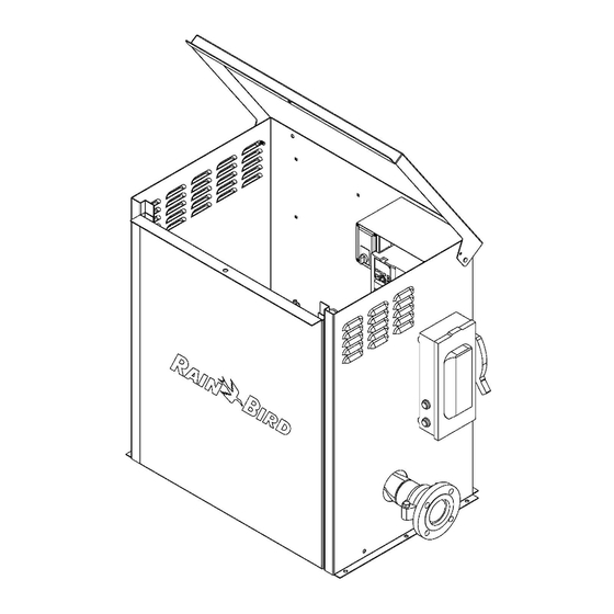
4 COMPONENT LOCATIONS 4 Component Locations Pump Station Layout Identify the location of components and controls of the pump station by comparing Table 4-1 with Figures 4-1 and 4-2. Description Flanged Discharge Connection Priming Port Discharge Ball Valve Auto-Off-Manual (AOM) Switch Box (contains Pump Start Relay) Auto-Off-Manual (AOM) Switch Discharge Pressure Gauge... -
Page 9: Mechanical Installation
Always make sure the pump station is mechanical installation for this pump station, disconnected from any electrical power source contact Rain Bird Global Service Plan (GSP) before beginning mechanical installation. support. See 1 Introduction for contact information. Note the CLPRS Model and the Job 1. - Page 10 5. Anchor the pump station to the concrete slab using the 8 mounting holes provided at the base of the pump station. Rain Bird recommends using 3/8” x 2-3/4” stainless steel wedge type anchors. Follow all local, state, province and national construction codes when selecting anchors.
- Page 11 5 MECHANICAL INSTALLATION source. See Appendix B – Suction Line side of the enclosure near the hinge pin And Foot Valve Guide for guidance on with the other. Disengage the plunger pin selection and installation of foot valves. The from the hole adjacent to the hinge pin flapper of the foot valve must be closed when before lowering the hood.
-
Page 12: Electrical Installation
Position. Should you have any questions regarding the electrical installation for this pump station, contact Rain Bird Global Service Plan (GSP) support. See 1 Introduction for contact information. Note Leaving the hood in the raised position without the CLPRS Model and the Job Number found on... - Page 13 Figure 6-3). If moisture is present, do not proceed. 9. Connect the power leads to the appropriate Contact Rain Bird Global Service Plan (GSP) terminals in the Fused Electrical Disconnect. support. See 1 Introduction for contact a. For single phase, connect power leads to information.
- Page 14 6 ELECTRICAL INSTALLATION 12. If your system is an asymmetric grounding power system the Radio Frequency Interference (RFI) jumper will need to be Sharing the earth ground of the pump station with removed. other equipment could result in interference with a.
- Page 15 6 ELECTRICAL INSTALLATION with the other. Disengage the plunger pin from the hole adjacent to the hinge pin before lowering the hood. See Figure 5-2. 17. If the pump station is to be used with an external input from an irrigation controller (Clock Start), proceed to 7 Connecting An External Input section.
-
Page 16: Connecting An External Input
Decoder type irrigation controllers such as the irrigation controller (Clock Start) to signal the VFD Rain Bird ESP-LXD, use a single pair of wires to to wake the pump station (see Wake / Start control multiple irrigation valves by using a signal... - Page 17 Raise the pump station hood. Ensure that 8. For decoder type irrigation controllers such as the retractable spring plunger pin on the the Rain Bird ESP-LXD with the Rain Bird FD- left side of the enclosure near the hinge 102 Decoder: pin is engaged in the hole adjacent to the a.
- Page 18 7 CONNECTING AN EXTERNAL INPUT b. Have a firm grip on the pump station hood with one hand, while pulling the knob of the retractable spring plunger on the left side of the enclosure near the hinge pin with the other. Disengage the plunger pin from the hole adjacent to the hinge pin before lowering the hood.
-
Page 19: Priming The Pump - Suction Lift Applications
Should you have any questions regarding priming left side of the enclosure near the hinge the pump, contact Rain Bird Global Service Plan pin is engaged in the hole adjacent to the (GSP) support. See 1 Introduction for contact hinge pin on the cover. - Page 20 8 PRIMING THE PUMP – SUCTION LIFT APPLICATIONS Disengaging the retractable spring plunger pin from the hole adjacent to the hinge pin without having a firm grip on the pump station hood could result in death or serious injury. Always have a firm grip on the pump station hood before disengaging the retractable spring plunger pin Table 8-1.
-
Page 21: How The System Works
9 HOW THE SYSTEM WORKS 9 How The System Works the VFD (H, Figure 4-1). For Suction Lift Systems General (see Appendix A – Pump Intake Applications), either the Clock Start or Time Of Day Start is The Compact Low Profile Rapid Ship (CLPRS) used. - Page 22 9 HOW THE SYSTEM WORKS The pump station will exit the Pipe Fill Mode after the pressure threshold has been reached, or a configured time period has elapsed. The Pipe Fill Mode can be enabled or disabled. Water Hammer or hydraulic shock is a pressure surge or wave caused when fluid in motion is forced to stop or change direction suddenly.
-
Page 23: Operator Interface
Figure 10-2. System Status Screen User Menu And VFD Menu There are separate menus for Rain Bird configuration and the VFD configuration. The User Menu for Rain Bird configuration is accessed by pressing the Menu key from the System Status screen. Pressing the key will access the VFD Menu for VFD configuration. - Page 24 The pump station input and output status can be shown in Figure 10-5. Use the checked by pressing the I / O key when in keys to select from the Rain Bird Main Menu. the System Status screen. Pressing Next key will cycle through the screens. Open circles next to an input or output indicates an OFF state.
- Page 25 10 OPERATOR INTERFACE Figure 10-7. Checking Input / Output Status. Station Statistics (Stats) The pump station System Statistics can be accessed by pressing the Stats key in the System Status screen. While in the Statistics screen, pressing the R-kW key will reset the accumulated kilowatt hours used.
-
Page 26: Setting Variable Frequency Drive Parameters
11 SETTING VARIABLE FREQUENCY DRIVE PARAMETERS 11 Setting Variable Frequency Drive Parameters Method 2 General If the settings in the menu screen appear as in The Variable Frequency Drive (VFD) parameters Figure 11-2, select the item to be changed with may be accessed and set by the user. -
Page 27: Initial Start-Up Guide
12 INITIAL START-UP GUIDE 12 Initial Start -Up Guide 2. If it is necessary to remove the front cover, General remove the six screws located on the inside of the pump station enclosure and lift the front The Initial Start-Up Guide is intended to get the cover away from the flanges on either side of Compact Low Profile Rapid Ship (CLPRS) pump the enclosure. - Page 28 12 INITIAL START-UP GUIDE manufactured, the pump motor shaft must be rotated by hand to ensure that the shaft rotates freely, and the pump motor bearings are properly lubricated. If 6 months or longer has elapsed since the pump station has been manufactured, the pump motor bearings may need to be greased before starting the pump.
- Page 29 8. If the voltage set in the VFD is not as stated 3. Use the keys to scroll to 8: on the Job Information Label, DO NOT PROCEED FURTHER. Contact Rain Bird Time Setup. Press the key to select Global Service Plan (GSP) support. See 1 (see Figure 12-6).
- Page 30 1. Open the Discharge Ball Valve (C, Figure 4-1) confirm the Time Setup. See Figure 12-7. by placing the handle controlling the valve 8. Press the key to return to the Rain Bird butterfly parallel to the discharge piping. See Menu. Figure 12-8.
- Page 31 3. From the System Status screen, press the The Pipe Fill Mode allows the pump station to fill Menu key to get to the Rain Bird Main the irrigation system slowly when the pump is Menu screen (see Figure 12-10).
- Page 32 12 INITIAL START-UP GUIDE c. Be sure to save the new values by pressing the key when finished. Figure 12-12. Adjusting Pipe Fill Parameters. 8. Press the key 6 times to return to the Figure 12-11. Adjusting Parameters For Pipe Fill System Status screen.
- Page 33 1. A Flow Switch is either ON 3. From the System Status screen, press the (1) or OFF (0). Menu key to get to the Rain Bird Main 11. From the first Wake Configuration settings Menu screen (see Figure 12-13).
- Page 34 Irrigation Controller in 7 Connecting An 2. From the System Status screen, press the External Input section. Menu key to get to the Rain Bird Main 2. Set the AOM Switch (E, Figure 4-1) in the OFF Menu screen (see Figure 12-13).
- Page 35 See Figure 6-2. have the same start time and run time. 2. From the System Status screen, press the Menu key to get to the Rain Bird Main Menu screen (see Figure 12-18). 3. From the Rain Bird Main Menu screen, press Config key to get to the Configure menu (see Figure 12-18).
- Page 36 12 INITIAL START-UP GUIDE plus the Boost Pressure at minimum speed. 4. Press the Wake key to get to the Wake / To adjust the Boost Pressure setting, from the Sleep screen (see Figure 12-18). second Sleep Configuration settings screen, 5.
- Page 37 Set Point, the zone is demanding too little flow. Add flow to the zone to bring the On initial start-up of the pump, Rain Bird frequency above 35 Hz. recommends that the sprinklers be turned on or c.
- Page 38 12 INITIAL START-UP GUIDE i. Reduce the flow in the zone until the VFD can maintain the pump pressure Set Point, at a frequency slightly lower than 60 Hz. ii. Reduce the pump pressure Set Point, if the pump is operating outside the flow curve of the pump.
-
Page 39: System Alarms And Faults
Back The VFD records both System alarms related to key 4 times will return you to the System Status pump station operation (Rain Bird configuration), screen. and VFD alarms specific to the VFD (VFD Variable Frequency Drive Alarm configuration). - Page 40 Before resetting any alarm, determine the reason 2. Determine the reason or cause of the alarm or cause of the alarm and correct the problem. and correct the problem. Common Rain Bird System Alarms Alarm Description Possible Causes High Pressure Pump pressure is above •...
- Page 41 13 SYSTEM ALARMS AND FAULTS of rated Full Load Amps • Pump motor is not rotating freely. See Item 8 in 14 (FLA). Troubleshooting section. • Pump discharge parameters set beyond capabilities of pump as stated on the Pump Flow Curve. •...
- Page 42 13 SYSTEM ALARMS AND FAULTS Overheat 2 An oH2 warning occurs • Ventilation openings in pump station Warning when a board-level enclosure are blocked. component temperature is • Exhaust fans (if installed) are higher than the oH2 obstructed or not operational. warning level.
- Page 43 13 SYSTEM ALARMS AND FAULTS Ground Fault Ground fault occurs when Note: the short circuit protection is (one of) the output provided for the AC motor drive terminal(s) is grounded, protection, and not to protect the user. and short-circuit current is greater than Pr.
-
Page 44: Troubleshooting
14 TROUBLESHOOTING 14 Troubleshooting To check pump station Statistics, see Station General Statistics (Stats) in 10 Operator Interface section. This section is intended to give basic guidance when troubleshooting the Compact Low Profile To check pump station Alarms, see System And Rapid Ship (CLPRS) pump station. - Page 45 14 TROUBLESHOOTING Red Pump Station Alarm If illuminated see Problem No. 5. Light is illuminated. • Pump Start Relay is not Verify that the irrigation controller is receiving a signal from the properly connected to the Pump Start external input. Relay.
- Page 46 See System And Variable Frequency Drive Alarm Light is Operator Interface to Alarms in 13 System Alarms and Faults illuminated. determine possible cause. section for Alarm and Possible Causes. Correct the problem and reset the alarm. If the alarm persists, consult Rain Bird GSP support.
- Page 47 14 TROUBLESHOOTING Pump continues to Stuck or leaking valve in the Repair stuck or leaking valve. run after irrigation has irrigation field. ended. Parameters for Sleep Check and set the parameters for Sleep Configuration not properly Configuration. See Sleep Configuration in set.
- Page 48 14 TROUBLESHOOTING 5. Ensure that all wiring connections are tight both at the VFD and the pump motor. Re-install wire nuts or split bolts in the pump motor junction box as necessary. 6. Close the VFD enclosure, and the pump motor junction box.
-
Page 49: Maintenance
Read and understand all instructions, hazard Authorized Service Provider. Extended warranty warnings and relevant appendices before options are also available. Contact the Rain Bird beginning pump motor bearing greasing. GSP team at 1-866-477-9778 for information. To grease pump motors with grease fittings: Should you have any questions or issues 1. - Page 50 15 MAINTENANCE Working with electrically energized components in the pump station enclosure will result in death or serious injury. Always make sure the Fused Electrical Disconnect on the pump station is OFF, and that proper Lockout / Tagout procedures are followed before beginning winterization of the pump station.
- Page 51 Damage to the pump station caused by improper or incomplete winterization is not covered under 1. Remove the padlock or zip-tie from the pump the Rain Bird Customer Satisfaction Policy. station enclosure lid. Always follow the winterization procedure to 2. Verify that the Discharge Isolation Valve is prevent damage to the pump station.
-
Page 52: Appendix A - Pump Intake Applications
APPENDIX A – PUMP INTAKE APPLICATIONS Appendix A – Pump Intake Applications Flooded Suction Intake water may be supplied to the pump station by any of three different applications. In Flooded Suction applications the pump is fed from a vented tank with a water level above the Pressure Boost pump station. -
Page 53: Appendix B - Suction Line And Foot Valve Guide
APPENDIX B – SUCTION LINE AND FOOT VALVE GUIDE Appendix B – Suction Line And Foot Valve Guide 5. Avoid elbows or bends in the suction line. If Improperly installed suction lines and / or foot and elbow in the suction line is necessary, valves can be troublesome when pump stations provide a straight pipe with a minimum length are used in Suction Lift applications. -
Page 54: Appendix C - Power Grounding Systems
APPENDIX C – POWER GROUNDING SYSTEMS Appendix C – Power Grounding Systems systems to prevent grounding through the filter The Delta Variable Frequency Drive (VFD) capacitors and causing damage to the VFD. contains a Radio Frequency Interference (RFI) jumper that, when installed on a symmetric Table C-1 shows symmetric and asymmetric (balanced) 3-phase power system, will protect the grounding power systems.
Need help?
Do you have a question about the CLP03AAC4RS and is the answer not in the manual?
Questions and answers