Table of Contents
Advertisement
Quick Links
G-Force
INSTRUCTION FOR INSTALLATION, OPERATION, AND MAINTENANCE
DANGER
SAFE OPERATING RANGE FOR MONITOR OUTLET:
Up to 2500 gpm below 130 psi (9500 L/min @ 9 bar)*
Up to 2000 gpm below 200 psi (8000 L/min @ 14 bar)*
Up to 1600 gpm @ 300 psi maximum (6000 L/min @ 21 bar)*
*these maximum flow rates and nozzle inlet pressures are
valid for monitor outlets up to 18.6" (472 mm) tall from the
IVUM outlet.
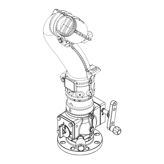
(shown from gearbox side)
Model ZAAZT-RC or ZASZT-RC
with 2.5" NH Quick Connect for Tornado
(shown from gearbox side)
TASK FORCE TIPS LLC
MADE IN USA · tft.com
©Copyright Task Force Tips LLC 2013-2024
4" Industrial Valve Under Monitor
Understand manual before use. Operation of this device without understanding the manual and
receiving proper training is a misuse of this equipment. Obtain safety information at tft.com/
serial-number.
This equipment is intended for use by trained and qualified emergency services personnel for
firefighting. All personnel using this equipment shall have completed a course of education
approved by the Authority Having Jurisdiction (AHJ).
This instruction manual is intended to familiarize firefighters and maintenance personnel with the
operation, servicing, and safety procedures associated with this product. This manual should be
kept available to all operating and maintenance personnel.
Model ZAAZ3 or ZASZ3
with 4" ANSI 150 Outlet
IVUM and IVUM RC
HYDROSTATIC PROOF TEST: 1200 psi (83 bar)**
**Do not exceed the rated operating pressure of 300 psi (21 bar).
The hydrostatic proof test is performed on a sample valve to ensure
it does not visibly rupture, crack or permanently distort at 4 times the
rated operating pressure. The purpose of the proof test is to be
confident the valve design may be safely operated at the rated
operating pressure.
Model ZAAZX or ZASZX
for Integrated TFT Monitor
(shown from secondary position indicator side with Y5-D21A-Z)
3701 Innovation Way, Valparaiso, IN 46383-9327 USA
1
800-348-2686 · 219-462-6161 · Fax 219-464-7155
LIZ-050 April 10, 2024 Rev05
Advertisement
Table of Contents

Summary of Contents for TFS IVUM
- Page 1 G-Force IVUM and IVUM RC 4” Industrial Valve Under Monitor INSTRUCTION FOR INSTALLATION, OPERATION, AND MAINTENANCE Understand manual before use. Operation of this device without understanding the manual and DANGER receiving proper training is a misuse of this equipment. Obtain safety information at tft.com/ serial-number.
- Page 2 DANGER PERSONAL RESPONSIBILITY CODE The member companies of FEMSA that provide emergency response equipment and services want responders to know and understand the following: Firefighting and Emergency Response are inherently dangerous activities requiring proper training in their hazards and the use of extreme caution at all times. 2.
-
Page 3: Table Of Contents
3.2 VARIOUS MODELS AND TERMS/INTENDED ORIENTATION 3.3 CORROSION 3.4 USE WITH SALT WATER 3.5 IVUM OVERALL DIMENSIONS 3.6 IVUM RC OVERALL DIMENSIONS 3.7 SIDE B MONITOR OUTLET OPTIONS 4.0 INSTALLATION 4.1 STRUCTURAL REQUIREMENTS FOR PIPE FLANGE MOUNTED MONITORS 4.2 FLANGE INSTALLATION 4.3 MONITOR INSTALLATION AND COMPATIBILITY... -
Page 4: Meaning Of Safety Signal Words
MEANING OF SAFETY SIGNAL WORDS A safety related message is identified by a safety alert symbol and a signal word to indicate the level of risk involved with a particular hazard. Per ANSI Z535.6, the definitions of the four signal words are as follows: DANGER indicates a hazardous situation which, if not avoided, will result in death or serious injury. -
Page 5: General Information
GENERAL INFORMATION The 4” Industrial Valve Under Monitor (IVUM) is a robust, low friction loss valve intended for installation directly beneath monitors on standpipes with 4” ANSI 150 or DN 100 PN16 flange connections. Dual reflective valve position indicators allow 360 degree visual confirmation from a distance in all light conditions. -
Page 6: Various Models And Terms/Intended Orientation
RETAINER THREADS DRAIN VALVE SIDE 'A' INLET FLANGE VALVE SEAT RETAINER WITH SPANNER NOTCHES 4" ANSI 150 AND DN100 PN16 Figure 3.2A IVUM RC PARTS IDENTIFICATION MANUAL OVERRIDE KNOB SERIAL NUMBER MODEL NUMBER RC ACTUATOR MOTOR Figure 3.2B CORROSION All valve bodies are hard anodized aluminum which is powder coated inside and out to help prevent corrosion. Galvanic corrosion due to dissimilar metals can be minimized by using flange isolation kits and an anti-corrosive lubricant such as Dow Corning 112 Silicone Grease. -
Page 7: Ivum Overall Dimensions
IVUM OVERALL DIMENSIONS The overall height and weight of the IVUM vary according to the side ‘A’ inlet material and choice of side ‘B’ outlet to monitor. The overall height and weight can be calculated by adding the values for the appropriate options shown in section 3.5... -
Page 8: Ivum Rc Overall Dimensions
6.6" [168mm] Ø8.9" [226mm] Figure 3.6 IVUM WEIGHT WITHOUT MONITOR OUTLET MODEL SIDE A Option for Flange, Seat Retainer, and Half Ball WEIGHT - lb (kg) ZAAD*-RC Hard anodized Aluminum with internal drain in half ball 26.0 (11.8) ZAAZ*-RC Hard anodized Aluminum without drain in half ball 26.0 (11.8) -
Page 9: Side B Monitor Outlet Options
QUICK CONNECT - 2.5”NHM (for Tornado) Y2432A.4 TORNADO INTEGRATED BASE FOR VUM (built-into Tornado monitors Y2-TV1A and Y2-EV1A only) LARGE MONITOR INTEGRATED BASE FOR IVUM (built-in to Monsoon, Typhoon & Hurricane monitor models with ‘X’ inlet option) Table 3.7 OPTION 1 PART# A1026.4 OPTION 2 PART# A1040.4... -
Page 10: Installation
INSTALLATION Mismatched or damaged waterway connections may cause equipment to leak or uncouple under CAUTION pressure. Failure could result in injury. Equipment must be mated to matched connections. Dissimilar metals coupled together can cause galvanic corrosion that can result in the inability to CAUTION uncouple the connection, or complete loss of engagement over time. -
Page 11: Flanged Monitors (Side B Options 3, 4, And V)
4.3.1 FLANGED MONITORS (Side B options 3, 4, and V) Install monitor on valve using the alternating bolt tightening sequence shown in figure 4.2. • For options 3 and 4, install a ring gasket and tighten 5/8-11 bolts or studs to 76-80 ft-lb (100-110 N·m). •... -
Page 12: Code-Rpm Direction Connection (Side B Options 1 And 2)
4.3.4 CODE-RPM DIRECTION CONNECTION (Side B options 1 and 2) ® 1. Apply blue Loctite to the threads on both Cylinder Nuts. 2. Align the grooves in the heads of the Cylinder Nuts with the top sides of the Clamps. 3. -
Page 13: Electronic Installation And Wiring
To control the valve from a TFT RC monitor operator station, the valve’s Blue and White communication wires must be connected to the monitor’s blue and white wires as described in section 2.0 of LIY-500 RC MONITOR ELECTRICAL CONTROLS SUPPLEMENT. Figure 4.4 shows the IVUM RC typical interface box connections. ELECTRIC MOTOR TYPICAL INTERFACE BOX... -
Page 14: Interface Enclosure Mounting
4.4.1 INTERFACE ENCLOSURE MOUNTING Select an enclosure location. The enclosure is designed to be surface mounted and the size is 4 3/4 x 6 3/4 (120 mm x 170 mm). Height of enclosure is 2 1/4” (57 mm). A full size template is provided below. MOUNT ENCLOSURE WITH (2) 1/4-20 FASTENERS TIGHTEN SECURELY... -
Page 15: Inputs Signal Configuration
AUX BUTTON OPERATION The IVUM RC can be operated from any TFT RC Monitor operator station equipped with AUX 1/AUX 2 buttons. The IVUM RC is factory configured to operate from the AUX 2 button, but can be changed to operate from the AUX 1 button. To change AUX button operation: POWER LED 1. -
Page 16: Use
Each IVUM RC is shipped with several button overlays with adhesive that can be attached to any RC monitor operator station with an AUX button. If additional overlays are needed, contact the factory. To apply the overlay: 1. Clean operator station surface to remove any oils or residues. -
Page 17: Electric Remote Control Operation
ELECTRIC REMOTE CONTROL OPERATION Power LED: • LED will be solid green when power is present. • Flashing green LED indicates low voltage. Changing Modes (Unit is shipped from factory in the Automatic Mode): • Activate CLOSE and STOP inputs together for 3 seconds to change to Automatic Mode. •... -
Page 18: Use On Telescoping Waterways (Aerial Apparatus)
After pressure has been relieved, the internal drain valve allows water and atmospheric air to back flow through the monitor and IVUM to drain the waterway, even if the IVUM remains closed. Then, the internal drain valve allows air to vent out to the atmosphere as the waterway is retracted. -
Page 19: Warranty
WARRANTY Task Force Tips LLC, 3701 Innovation Way, Valparaiso, Indiana 46383-9327 USA (“TFT”) warrants to the original purchaser of its products (“equipment”), and to anyone to whom it is transferred, that the equipment shall be free from defects in material and workmanship during the five (5) year period from the date of purchase for mechanical components, and the two (2) year period from the date of purchase for electrical components. -
Page 20: Maintenance
MAINTENANCE TFT products are designed and manufactured to be damage resistant and require minimal maintenance. However, as the primary firefighting tool upon which your life depends, it should be treated accordingly. The unit should be kept clean and free of dirt by rinsing with water after each use. -
Page 21: Crankshaft Override And Replacement
1. Close the upstream water supply and relieve pressure leading up to the valve. 2. Locate 1/2” hex where crankshaft protrudes from opposite side of gearbox. For IVUM RC models, it will be necessary to remove the chain cover using a 3/16” Allen wrench, then remove the chain and sprockets. -
Page 22: Side B Monitor Valve Seat Replacement
8.4.4 SIDE B MONITOR VALVE SEAT REPLACEMENT The valve seat may be replaced in the field if it becomes a source of leakage due to harsh environmental conditions or excessive age. A ½” drive spanner wrench for the valve seat retainer may be purchased from Task Force Tips. To replace the valve seat: 1. - Page 23 This page intentionally left blank. ©Copyright Task Force Tips LLC 2013-2024 LIZ-050 April 10, 2024 Rev05...
-
Page 24: Exploded View And Parts Lists
EXPLODED VIEW AND PARTS LISTS Exploded views and part lists are available at tft.com/serial-number. 10.0 OPERATION AND INSPECTION CHECKLIST BEFORE EACH USE, equipment must be inspected to this checklist: All valves open and close fully and smoothly. 2. Waterway is clear of obstructions. 3.
Need help?
Do you have a question about the IVUM and is the answer not in the manual?
Questions and answers