
Summary of Contents for RMD Components CReel 3.0 WB
- Page 1 3.0 WB Model: 3.0 WB Charging station Installation Manual V 1.01 Installation manual V 1.01...
- Page 2 3.0 WB Document: Mod. 8.3 - CReel 3.0_WB - UM_ENG_Rev.1.01 Pages: XX Specifications are subject to change due to further technical developments. Details presented may be subject to correction. All rights reserved. © R.M.D. Components Italia S.r.l. Via Avigliana 24 - 10040 - Rivalta di Torino (TO) - Italia +39.011.78.010.78, +39.011.78.011.75, info@rmdcom.com For information on R.M.D.
- Page 3 3.0 WB Index Index 9. Configuration 1. General notes 9.1 RFID reader 1.1 Manufacturer notes 1.2 Installation Warnings 10. Commissioning 2. Introduction 10.1 Performing safety checks 2.1 Purpose of this document 11. Repair 2.2 Requirements 11.1 Replacing the fuse 2.3 Intended use 11.2 Error and fault rectification 2.4 Safety Warnings 11.3 Software update 2.5 Warranty 12. Disposal 2.6 About this document 2.6.1 Contents of this document 12.1 Disposal of the device 2.6.2 Topics not covered in this document...
-
Page 4: Installation Warnings
3.0 WB General notes General notes 1.1 Manufacturer notes The product’s manufacturer is © R.M.D. Components Italia S.r.l. Via Avigliana 24 - 10040 - Rivalta di Torino (TO) - Italia 1.2 Installation Warnings WARNING! Non-compliance with the safety instructions can result in serious injury or death and damage to the device! R.M.D. -
Page 5: Purpose Of This Document
3.0 WB Introduction Introduction 2.1 Purpose of this document This document describes the complete installation of the CReel 3.0 device. This document serves as a supplement to the manuals supplied with the CReel 3.0 device. All instructions and safety warnings in the manuals supplied must be observed! The pictures and drawings depicted in this manual are for illustrative purposes only. -
Page 6: Intended Use
3.0 WB Introduction 2.3 Intended use The device is intended for charging electrically powered vehicles (e.g. electric cars). The connection of other devices (e.g. power tools) is not permitted. The device is suitable for use both indoors and outdoors. The device can be mounted vertically on a wall or column, or vertically on the ceiling. -
Page 7: Safety Warnings
3.0 WB Introduction 2.4 Safety Warnings In various places in the manual you will find indications and warnings of possible dan- gers. The symbols used in conjunction with words have the following meanings: DANGER! Means that failure to take precautionary measures will result in serious injury or even death. -
Page 8: Warranty
3.0 WB Introduction 2.5 Warranty Only repair work expressly permitted by RMD Components Italia S.r.l. may be carried out. Any other handling of the device will result in the loss of warranty rights. WARNING! Danger due to electric shock and fire hazard! After opening the back, the safety of the product can no longer be guaranteed. -
Page 9: About This Document
3.0 WB Introduction 2.6 About this document This manual is an integral part of the product. It must be retained for the entire life of the product and, if the product is sold or transferred, must be handed over to the new owner or user of the product. -
Page 10: Safety Regulations
3.0 WB Safety Regulations Safety Regulations WARNING! Danger due to electric shock and fire hazard! • Installation, initial operation, maintenance or retrofitting of the device may only be carried out by qualified, authorised and appropriately trained electro-technicians1) who are fully responsible for compliance with the applicable installation standards and regulation. -
Page 11: Package Contents
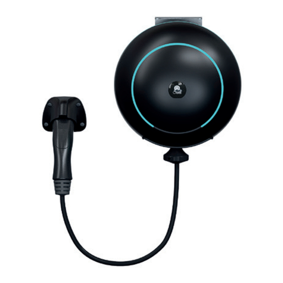
3.0 WB Safety Regulations / Package contents Caution Possible damage to property! • Any protective films may only be removed after the cables have been connected. • Disconnect the charging cable from the plug-in connection by pulling it only from the connector holder and not from the cable. •... - Page 12 3.0 WB Device description Device description 5.1 Front view Led rods Mains connection cable Charging cable Connector holder Information Depending on the device version, the charging socket or the charging cable may differ in shape from the one shown here. Installation manual V 1.01 Pag.
-
Page 13: Rear View
3.0 WB Device description 5.2 Rear view Cooling openings Mains connection cable outlet Brake cable Identification label 5.3 Bottom view Charging cable outlet Sliding cylinders Installation manual V 1.01 Pag. 10... - Page 14 The identification plate is located on the rear side of the device. The following figures show all the information that can be found on the type plate. The data on the type pla- te may differ depending on the device variant. RMD Components Italia S.r.l Local Contact: P +39 (0) 011 7801078 Email: info@rmdcom.com...
-
Page 15: Overview Of Variants
3.0 WB Device description 5.5 Overview of variants The type and equipment of the device can be identified by the product designation. The product designation can be found on the type label. Due to technical or legal limitations, not all variants/options are available in all countries. - Page 16 3.0 WB Indications and control elements Indications and control elements 6.1 LED bar LED bars inform about the current operating status of the charging station. These consist of 2 rings that can light up or flash in different colours. The LED bars are only visible when the power supply is switched on. Color code Meaning Soft green LED...
-
Page 17: Mounting And Installation Instructions
3.0 WB Mounting and installation instructions Mounting and installation instructions The device must be mounted vertically on a wall or column, or on the ceiling. The fixing kit is suitable for concrete, bricks. In the case of different substrates, a suitable type of fixing must be selected. - Page 18 3.0 WB Mounting and installation instructions 7.1 General criteria for the choice of location The device has been constructed for both indoor and outdoor environments. It is therefore necessary to ensure the correct installation conditions and protection of the device at the installation site. The following criteria must absolutely be considered when selecting the location: •...
-
Page 19: Required Tools
3.0 WB Mounting and installation instructions 7.2 Space needed 20 cm If several adjacent charging stations are installed, a distance of at least 200 mm must be maintained between them. Information We recommend mounting the charging station at a height of 170 cm and the charging socket at a height of 120 cm, or for wheelchair users between 90 cm and 110 cm the charging station and a suitable height for the charging socket. -
Page 20: Mounting The Device
3.0 WB Mounting and installation instructions 7.4 Mounting the device The CReel 3.0 can only be mounted in a vertical position with the cable outlet pointing downwards. 1700 mm 900 ÷ 1100mm We recommend installation approximately 170 cm above the ground or between 90 cm and 110 cm for wheelchair users. - Page 21 3.0 WB Mounting and installation instructions 7.4.1 Description of support bracket The support bracket provides, in addition to the wall or ceiling installation mode, the possibility of accommodating the CReel 3.0 in tilt or static mode. Use the holes as in Fig.
-
Page 22: Ceiling Installation
3.0 WB Mounting and installation instructions 7.4.3 Ceiling installation Use the drilling template (page XX) to drill the 3 holes correctly 1) Remove the bracket from the CReel 3.0 2) Screw the bracket with 3 screws and washers provided (Fig.4) a) Static mode 3) Position the CReel 3.0 and insert the fi rst long bolt into the bracket (Fig.5a) 4) Insert the second long bolt to fi nish the installation (Fig.6a) Fig. -
Page 23: Voltage Supply
3.0 WB Mounting and installation instructions / Connections and wiring 7.4.4 Installation with padlock (optional) Follow the instructions in chapter 7.4.1 or 7.4.2 depending on the type of installation chosen up to point 3) 4) Insert the short bolt as indicated (Fig.7) 5) Insert the padlock as indicated to fi nish the installation (Fig.8) Fig. - Page 24 3.0 WB Connections and wiring No other consumers may be connected to this circuit. An RCD of at least type A must be used, as all variants of the CReel 3.0 have internal monitoring of continuous fault currents ≥ 6 mA, alternating currents ≥ 30 mA. Other important points such as ‘cascading’...
-
Page 25: Voltage Supply Connection
3.0 WB Connections and wiring 8.2.2 Voltage supply connection The device is supplied with 2.5 m of cable for connection to the mains, depending on the version purchased the cable colours to be observed are as follows: Single-phase version (220/230V) Pilot Three-phase version (380/400V) Pilot ATTENTION! -
Page 26: Rfid Reader
3.0 WB Configuration / Commissioning Configuration The device is sold pre-configured with an electrical power output of 6 A. Further configuration is to be done via the webapp, for details see the webapp manual. 9.1 RFID reader The device is equipped with an RFID card reader that enables the functionality only for owners of such cards correctly configured on their CReel 3.0. - Page 27 3.0 WB Commissioning 10.1 Performing safety checks Before the first start-up, check the effectiveness of the system’s protective measures according to the applicable national regulations. Electrical systems or appliances must be checked by the installer of the system or appliance before the first start-up. This also applies to the extension or modification of existing electrical systems or devices.
-
Page 28: Replacing The Fuse
3.0 WB Repair 11. Repair 11.1 Replacing the fuse In the event of overheating, the device is equipped with several safety levels, the last of which is a non-resettable thermal fuse. If all reset procedures (see error and solution table) do not solve the problem, please contact customer service for a fuse replacement. Replacement can only be carried out by the manufacturer. - Page 29 3.0 WB Disposal 12. Disposal 12.1 Disposal of the device Attention Observe the regulations for the disposal of electrical and electronic equipment! The symbol of the crossed-out wheeled bin means that electrical and electro- nic equipment must not be disposed of with household waste. The materials are recyclable according to the relevant marking.
-
Page 30: Power Supply
3.0 WB Technical data 13. Technical Data 13.1 General information Mode 3 according to IEC 61851-1 Charging mode AC charging Overvoltage category III according to EN 60664 Protection class Degree of protection IP44 Protection against mechanical IK08 shock < 10 kA Short-time current withstand (rms according to EN 61439-1) Continuous internal fault current... -
Page 31: Environmental Conditions
3.0 WB Technical data 13.4 Environmental conditions Indoor and outdoor environments Access restrictions at Limited and unrestricted access installation site Mounting (static) Wall or column or ceiling Operating temperature -25 °C to +50 °C 16 A (without direct sunlight) -25 °C to +40 °C 32 A (without direct sunlight) Storage temperature... -
Page 32: Dimensions And Weight
3.0 WB Technical data 13.5 Interface WiFi IEEE 802.11 b,g,n, 2,4 GHz Mode AP Ad-hoc-Mode, Client Mode 13.6 Dimensions and weight Height 326 mm Width 326 mm Depth 260 mm Weight Approx. 10 Kg The actual footprint varies depending on the location of the wall mount and charging connector. 326 mm 260 mm 326 mm... - Page 33 3.0 WB Technical data 13.7 EU Directives and Standards 2014/35/UE Low Voltage Directive 2014/30/UE Electromagnetic Compatibility Directive 2014/53/UE Radio Equipment Directive (RED) Restriction of the use of Hazardous 2011/65/UE Substances (RoHS) Directive on Waste electrical and 2012/19/UE electronic equipment (WEEE) Installation manual V 1.01 Pag.
-
Page 34: Declaration Of Conformity
3.0 WB Declaration of conformity 14. Declaration of conformity Installation manual V 1.01 Pag. 31... - Page 35 3.0 WB Installation manual V 1.01 Pag. 32...
Need help?
Do you have a question about the CReel 3.0 WB and is the answer not in the manual?
Questions and answers