
Related Manuals for C&S CSENEX-I 250


Summary of Contents for C&S CSENEX-I 250
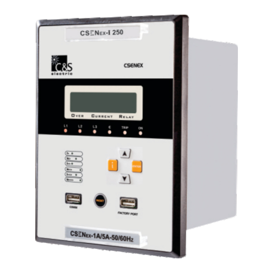
- Page 1 CSENEX-I 250 current Protection Relay This QRG will help you step-by-step installation, operation and programming procedure. Please go through all the instructions carefully prior to implementing. C&S Electric Limited...
-
Page 2: Safety Precautions
Safety Precautions This section provides full information on safe installation of this equipment. Personnel undertaking installation, commissioning or servicing work, should be familiar with this relay operation/working procedure and all input/output ratings. The equipment documentation should be consulted before installation, commissioning, or servicing the equipment. - Page 3 CSENEX-I Family of protective relays are numeric relays that provides multi protection and monitoring with reliable and fast protection solution in a single unit. In this family of CSENEX series, the CSENEX-I 250 is an feeder protection solution which has fast, sensitive and secure protection for feeder internal & external faults.
- Page 4 Front Interface of the Relay CSENEX Alpha Numeric V E R U R R E N T E L A Y TRIP UP Scroll / LED for Increment Key I> Pickup Ie> Enter Key & Fault I>> ENTER annunciation Ie>> Down Scroll / I>>>...
-
Page 5: Led Description
LED Description : indicates the fault in L1 phase : indicates the fault in L2 phase : indicates the fault in L3 phase : indicates the Earth fault for pickup TRIP : indicates the Earth fault for Trip : indicates the ON condition of the relay : indicates the pickup of Phase over current Low-set I>... - Page 6 Connection Diagram - 2 DI + 5 DO A1 A2 Earth L1 L2 L3 DI 1 Power Supply DI 2 D0 1 D0 2 D0 3 D0 4 D0 5 RS-485...
- Page 7 Recommended Terminal Lugs specifications Term Blocks Type/Cable Specifications Current Inputs Ring Type lug / 2.5mm or 4 mm control cable Auxiliary Supply Pin Type lug / 1.5 mm / 2.5 mm control cable Rear Comm. Port Pin Type lug / 1.5 mm / 2.5 mm control cable Front Comm.
-
Page 8: Measurement Accuracy
Measurement Accuracy Quantity Range Frequency Range Accuracy Current 0.05 - 30 xIp 50Hz + 2% / + 10mA Measuring Input Rated Data Rated current Ip :1A or 5A Rated frequency Fn : 50 Hz Drop out to Pickup Ratio >96% Reset Time 30 mSec Power consumption... - Page 9 Rear Port (RS-485) Communication Protocol MODBUS RTU / IEC 103 Baud rate selection (programmable) 4800/9600/19200/38400/57600 bps Parity selection (programmable) Even / Odd / None Stop bit 1 Bit Data bit 8 Bit data Remote Address (programmable) (1 to 247) Cable required for interface Two wire twisted shielded cable Relay Trip Contact Rating Contact Rating...
- Page 10 How to do Setting For setting below are simple steps for configuration: Default First Screen MAIN DEFAULT SCREEN PAGE: IL1 : 000.00A The very first Screen of the HMI shows the Measured IL2 : 000.00A current for all the phases based on CT ratio. <Menu 1>...
- Page 11 From Menu-1 : #COMMON SET# On selecting COMMON SETTING by pressing ENTER key, User can see the list of all the parameters by using the scroll keys. Press P-CTRatio 0001 ENTER to select the desired Parameter & use E-CTRatio 0001 ResetDly 00.0s Scroll keys to Edit the selected parameter.
- Page 12 From Menu-1 : # EVENT NUMBER # On selecting EVENT RECORD, by pressing SELECT ENTER key, Event no. screen appears. By using ←BACK ENTER & Scroll keys select the desired Event no. for its details. From Menu-1 : # DO ASSIGNMENT # On selecting DO ASSIGN, by pressing ENTER I>...
- Page 13 From Menu-1 : ERASE On selecting ERASE RECORD, by pressing ENTER key user can see the list of erase Events : NO parameters. Select either of the option by pressing Faults : NO ENTER key on it and use scroll keys. TRP_CNT : NO To save the desired changes, user have to enter the correct password by selecting the YES option.
- Page 14 From Menu-1 : On selecting COLD LOAD, by pressing ENTER # COLD LOAD # key. User can see the list of all the parameters by PhaseCh : DEFT using Scroll keys. Press ENTER to select the EarthCh : DEFT desired Parameter & use Scroll keys to Edit the I>...
-
Page 15: Dimension Details
Dimension Details CSENEX-I relay is available in a plastic case for panel or flush mounting Weight : Approx. 1.5 Kg (without cables) (All the dim. are in mm) 110.0 136.75 CSENEX V E R U R R E N T E L A Y TRIP I>... - Page 16 Trouble Shooting Points Remedy Problem Cause of Problem POWER ON LED Aux Power not 1) Check Aux. power supply / not glowing available/connected. connection Relay not inserted properly. 2) In a draw out model, re-install the relay firmly and smartly. Wrong connection/ Wrong measuring &...
Need help?
Do you have a question about the CSENEX-I 250 and is the answer not in the manual?
Questions and answers