Table of Contents
Advertisement
Advertisement
Table of Contents

Summary of Contents for smartflower POP
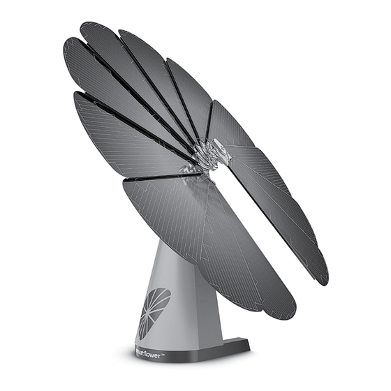
- Page 1 TECHNICAL HANDBOOK smartflower POP...
- Page 2 Version 1.0 | 2015-08-04 | version (EN)
- Page 3 S T R UC T UR E OF T HE H A NDBOOK Some of the topics are to be found in separate documents. 01 Technical Datasheet (separate document) 02 Loading & Packing Delivery / Transportation Conditions 03 Installation 04 Commissioning 05 User Manual (separate document) 06 Final Handover...
- Page 4 P RODUC T R E L AT E D DOC UME N T S SYSTEM HANDOVER PROCEDURE RELATED SEPARATE DOC. CONTENT Smart in Smart in technic and product dimensions detail technical data Sheet “smartflower™ POP“ Technical Datasheet Technic and electrical interfaces Detail country specific regulations As of: December 2014 Typing and printing errors reserved.
-
Page 5: Table Of Contents
S T R UC T UR E OF T HE H A NDBOOK Table of contents 01 Technical Datasheet 04 Commissioning Seaparate document Commissioning, electrical connections First startup 02 Loading & Packing Checks as per the acceptance log Delivery/transportation conditions Commissioning, settings Truck/transportation conditions Double function of... -
Page 7: Technical Datasheet
T EC HNIC A L D ATA S HE E T Technical Datasheet You will find the technical datasheet as a separate document. Note that the technical datasheet is to be seen as part of the technical handbook even it is an external document. -
Page 9: Loading & Packing
L O A DING & PA C K ING Loading & Packing Delivery/transportation conditions Truck/transportation conditions Double function of transportation guide Packing Accessory parts Reusable parts... -
Page 10: Delivery/Transportation Conditions
L O A DING & PA C K ING Delivery/transportation conditions The product is delivered with covers moun ted. Foot area for forklift is left open. Foot cover is stored inside the product’s housing. DO’S A ND DON T ’S Total product height including packaging material: 2.65 m F OR K L IF T DR I V E R S C A U T ION... -
Page 11: Truck/Transportation Conditions
Transportation guide Transportation guide Additional protection Fit 4 pcs anti slide Anti-collission 2 pcs wooden bars for belt tensioner each product spacer (5x8x900) outside Anti-colission spacer Fit 1pc woodenstick (10x10x900) between Pop’s single product two products side by side... -
Page 12: Double Function Of Transportation Guide
Please ask your local dealer for the smartflower damage report template. • The transportation guide MUST be removed latest prior to electrical installation! -
Page 13: Packing
L O A DING & PA C K ING Packing All accessories are mainly fixed inside the product’s rear cover. Parts according to part list are packed and fixed inside the rear cover dome and the product’s housing 1 screws and bolts product documentation windguard earthscrews (optional), etc. -
Page 14: Accessory Parts
L O A DING & PA C K ING Accessory parts AC CE S S ING T HE AC CE S S ORY PA R T S – R E U S A BL E PA R T S HO W T O R E MOV E T HE R E A R C OV E R DOME ? The following parts are primarily used for 1 open/remove 2 screws transportation and installation purposes. -
Page 15: Installation
IN S TA L L AT ION Installation Installation Pre checks Unloading Craning and positioning Adjustment on foundation... - Page 16 IN S TA L L AT ION Installation UNL OA DING, CR A NING A ND P O S I T IONING 2. On the truck remove the plastic packing and check for transport damages (scratch- 1. Pre checks es and bumps on the dome, the sidecovers, solar panels frontglass and siderails).
- Page 17 IN S TA L L AT ION Installation Remove forklift protection before fixing on 4. Craning and positioning the foundation is done otherwise when already fixed to the foundation resulting tension will not allow to remove the forklift protection any more! Remove protection rails and use for foundation fixing 5.
-
Page 19: Commissioning
C OMMIS S IONING Commissioning Commissioning, electrical connections First startup Checks as per the acceptance log Commissioning, settings... -
Page 20: Electrical Connections
C OMMIS S IONING Commissioning, electrical connection E L EC T R IC A L C ONNEC T ION S Minimum cross-section for cabling 2.5 mm2 to 30 m length is required as the Cable length cable cross-section for power minimum cross-section. - Page 21 C OMMIS S IONING Commissioning, electrical connection C ONNEC T P O W E R C A BL E S IN T HE DE V ICE ‚ Installation of anemometer is done by connecting the anemometer-plug to the ‚ Connect the power cable for home control cabinet.
-
Page 22: First Startup
C OMMIS S IONING First start-up Attention: smartflower must be started for the first time only by personnel certi- fied by smartflower energy technology GmbH. Commissioning by other persons automatically results in the loss of gua- rantee. NO T E During the first commissioning, the accep- tance log must be filled. -
Page 23: Checks As Per The Acceptance Log
C OMMIS S IONING Checks as per the acceptance log AT T E N T ION Follow the course in the acceptance log and first run all the visual checks. Refer to “certificate of acceptance” chapter 6 Final Handover”... -
Page 24: Commissioning, Settings
C OMMIS S IONING Commissioning, settings 3 Press the “confirm” key; the pass- Before commissioning for the first time, word field will be highlighted. Now you can the exact position and a possible deviation enter the password using the keys (PWD: for the south alignment must be updated 7357491). - Page 25 In the offset screen, you can enter a devia- tion, which is maximum of +/- 30 degrees, of smartflower from the south alignment. These deviations must be taken into account as shown in the figure. 6 Activate the selection using the “confirm”...
- Page 26 C OMMIS S IONING Commissioning, settings 5 In the next screen, you must enter the 8 The following screen allows to setup correct longitude for optimum sun tracking. the cleaning function frequency (daily, 1/ Example: Pinkafeld – longitude 16.125 week, 1/month, never) degree Modus next...
- Page 27 C OMMIS S IONING Commissioning, settings 10 The next settings is used to program the position in which the unit stays during the night (tracking/SIPO1/SIPO2/season) Modus next Tracking Select night position 11 If season mode is selected the last screen allows you to define a date frame in which the system moves into SIPO2 instead of SIPO1 to avoid problems with heavy snow...
-
Page 29: User Manual
U S E R M A NU A L User Manual You will find the user manual as a separate document. Note that the user manual is to be seen as part of the technical handbook even it is an external document. -
Page 31: Final Handover
F IN A L H A NDO V E R Final Handover Final Handover EC declaration of conformity... -
Page 32: Certificate Of Acceptance
F IN A L H A NDO V E R Certificate of Acceptance To be filled out together with the customer! Serial number: Date: Place: Type: SF Colour: RAL: Orientation The system is oriented to the south System differs from southern orientation: GPS coordinates: Customer Mr. - Page 33 F IN A L H A NDO V E R Final Handover TOPICS COVERED AND VERIFIED The final handover follows the document “Certificate of Acceptance / smartflower” customer & service partner details which is subject to go through together with the customer during installation by...
- Page 34 EC DEC L A R AT ION OF C OMP L I A NC E...
Need help?
Do you have a question about the POP and is the answer not in the manual?
Questions and answers