Table of Contents
Advertisement
Quick Links
Advertisement
Table of Contents

Summary of Contents for TARMOC TFT-2822X-SPLICER
- Page 1 SMOOTH RUNWAY FOR YOUR NETWORK...
-
Page 2: Table Of Contents
CONTENTS Preface......................... 1 Warnings and precautions................... 1 Technical Parameters................... 4 Standard configuration..................5 Machine introduction..................6 Key Function......................7 Main interface......................8 -Status bar/Information display area..............9 Splicing interface....................10 Detailed icon......................11 How to complete a splice..................12 -Prepare fiber....................... 12 -Place ment of optical fibers................13 -Protectionof splicing points- Heat shrink tubing....................14 Splicing setting..................... -
Page 3: Preface
Preface Thank you for buying fiber optic fusion splicer! This user manual explains how to install and use the fiber optic fusion splicer,To help you become as familiar as possible with the operation of the fusion splicer. Important! It isrecommended that all usersread this manual before usingthe fiberopticfusion splicer. ... - Page 4 cable,To preventthe riskoffire orelectric shock. 5.Do not expose the splicer to fire,Electric shock and rain or wet environment. 6.Please use only the dedicated adapter,Use of other adapters may cause damage to the splicer 7.When the fusion splicer encounters the following conditions,Please turn offthe fusion splicer immediately,Disconnect the adapter and remove the battery ...
-
Page 5: Technical Parameters
workabnormally. 3.Can be wiped with a silk cloth or soft fabric to clean the LCD screen. 4.Dependingon the viewing angle ofthe screen,The brightness ofthe monitor will also vary,And there may be some black,red, blue or green dots on the screen.These are notLCD monitorfailures,Itis a natural phenomenon. ... - Page 6 Splicing method Auto/Manual Splicingtime 8s (SMF typical value) Pull test 1.96-2.25N Image display Capacitive 5.5 inch touch LCD screen Magnification 300 (X/Y),150 (X/Y synchronization) Splicing method 1000 groups Typicalheatingtime Heating time 0-60s Heatshrinkable sleeve 20mm、30mm、40mm、50mm、60mm OPM Range(dBm):-70~+3/Wavelength:850nm-1625nm/Unc ertainty:±0.5% Red light (VFL) ≥10mW Operation interface GUl graphical user operation interface...
-
Page 7: Standard Configuration
Output voltage DC11.1V USB port output 5V/500mA Charger Input:AC100-240V,50/60Hz, Output: DC13.5V/4A Workingenvironment TEMP:-15℃C-+50℃C/RH;≤95%RH(non-condensing)/A SL:0-5000m/WS;≤15m/s Storage conditions Temperature:-40℃-+80°C/Humidity:0-95%/Battery:-20 ℃-+30°CLength Splicingmachineweight 190mmX146mmX117mm Splicingmachineweight 1.74KG (with battery),1.24KG (without battery) Data is forreference only,please refertothereal thing! Standard configuration 1. FiberOptic Splicing Machine,2.Cutter,3.Electrode rods,4.Stripper,5.Miller pliers, ... -
Page 8: Machine Introduction
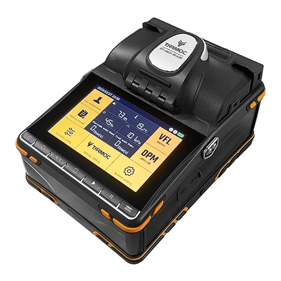
Machine introduction protection cover Heating tank Touch screen Operation buttons VFL interface Optical power meter USB port output Charging port Key Function Press to open the lid Power Key Long press to turn on or off. Reset key Underthe splicinginterface,Press the reset buttontoreset the horse to the original point,Status bar Shows the reset process and results. -
Page 9: Main Interface
Start key In splicing operation mode manual,Press the Continue button to start splicing,When pause is turned on,Press the Continue button to continue. Pause key Splicingprocess,Press the pause button,Currentoperation can be paused. Heating key In heating mode manual,Press the heating button to start heatingthe heating tank,Countdown to the start ofthe heating time in the upperleft corner ofthe splicing interface, Main interface... -
Page 10: Splicinginterface
a、Function icon Auto splicing mode Manual fusion mode Auto poweroff function on OPM open VFL open VFL timing b、Battery status Normal state Charging status Low battery reminder Information display area Altitude Ambient temperature Ambient humidity Ambient atmospheric pressure Note: a、Altitudes above 5000m, red digital display; b、ambient temperature is below-10℃C or above 50℃,red digital display;... -
Page 11: Detailed Icon
Splicingprocess,OPM values are notrefreshed,Function buttons in the shortcut control area 、Splicing settings、Function configuration all lock can not be operated. Detailed icon Pre-heating:After opening,After each successful splice,From the time the weatherproof cover is opened,Automatic heater start for6 seconds. Tensiletest:Afteropening,Tensiletest after each successful splice Save image:Afteropening,When the stitching iscomplete,Savethis stitched image. -
Page 12: How To Complete Asplice
atthe connection point based on thelight image,Some deviation from the real value.For reterence only,Cannot be used asthe basis for proiect acceptance, Splicing Pause:After opening,After fiber alignment is complete,Run Suspension:At this point, press to continue with the next step,Finish splicing Splicing tips: afteropening,the splicing process status barinformation tips area text tips,error pop-up boxtips. ... -
Page 13: Place Ment Of Optical Fibers
2、Placement ofoptical fibers Operation steps: ①Open protection cover from optical fiber lid ②Put the prepared fiber into the V-groove,and make sure that the end of the fiber is between the edge ofthe V-groove and the tip of the electrode (as shown in the figure below). -
Page 14: Protectionof Splicing Points-Heat Shrink Tubing
When〔Endface lnspection〕is on the,The fusion splicer will automatically check the fiber for damage and dust dust particles.Ifthe following conditions are detected in the fiber,Please remove the fiberand re-prepare it. note: When releasing fiber,Note the placement ofthe fiberinto the blue V-slot,The tip of the fiberis nearthe center ofthe electrode rod Center pointposition,Ifit is too far away or beyond the centeroftheelectrode rod,Both will prompt an error. -
Page 15: Splicing Mode
Splicing setting Splicing mode You can select the preset MM,SM,DS,NZDS four kinds ofsplicing mode,In addition,SET1,SET2, SET3and SET4 are provided forusers to set their own custom modes. Modify:The corresponding stitching mode parameters can be modified Note:The splicing process can be divided into two main steps:pre-fusing and splicing,We can change the discharge level during splicing by changing the relevant... - Page 16 steps. General splicing parameters are described in the following table: Parameter Description Parameter Description Center The position of the splicingnode whe Splicing voltage Used to set the intensity of arc re the arc is located during discharge discharge Splicing The position of the Splicingnode Pre-voltage Set the discharge voltage from...
- Page 17 Splicingsetting Splicing operation mode: Automatic:Splicing starts automatically as soon as the weatherproof cover is closed.Fiber should be preparedin advance,and put into the splicer. When open,Status bar display Manual:Afterthe windproof coveris closed,Press the start button to begin pairing fibers,After fiber alignment is complete,Run Suspension,Press the Start button to continue to the next step,Finish splicing.When open, Status bar display...
- Page 18 Heat mode: Set Auto/Manual mode. Heat shrink tube setting: 6differentthermoplastic tubes are preset in the splicingmachine, Forusers to choose,Customizabletemperature modification for each type,Selectthe best match forthe heat shrinktubingused. Heat temperature: Set heating temperature (130-230°C). Heating time: Setthetime from the startofheatingtotheend ofheating.Heating time is independent according to the surrounding temperature Adjustment,Longer or shorter heating time (0-60S).
-
Page 19: Function Config
Splicingsetting Preheat mode: When turned on,After each successful splice,From the moment of opening the weatherproof cover,Automatic heater start Preheating method: After setting open cover / after splicing. Preheating temperature: Set preheat temperature between 130-230℃C. Proheat time: Set the warm-up time between 5-30S. Function config Click to turn on/off or switch to the corresponding function ... - Page 20 Custom icon According to the user's needs,Shortcut control icons for thefunctions youwant touse,The settings here are displayed in the Quick Control Bar area at the bottom of the splicing screen,User-friendly. Click the icon in the display bar to delete the corresponding icon; Clickthe icon in the add bar to add it to the display bar.
-
Page 21: User Maintenance
User maintenance Brightness correction: Test and calibrate the sensitivity of two CMOS cameras. Electrode correction: Automatically calibrate the discharge intensity factor and fiber welding position. Motor calibration: Self-calibration motor speed. Camera dust detectiont: The weld machine automatically scans the camera image in rows and columns to detect dust and dirt that affect the observation results and may cause poor welding results. - Page 22 Select the [User Maintenance] [brightness correction]. Putin the stripped and cut optical fiber according to the prompt, and press the key to continue. start the automatic calibration is complete, the prompt"brightness correction success!"Close the prompt box and exit. Electroderod calibration When there is a sudden change in the external environment.Discharge intensity sometimes becomes unstable,This leads to increased splicing losses.Especially when the splicer is moved from low to high altitude,Needs some time to stabilize the...
-
Page 23: Motor Calibration/Camera Dustdetection
fails after completion,Please cut and place the opticalfiber again and repeat the above steps until the correction is successful,If prompted successfully,Correction completed,Close the prompt box and exit. note: ①Keep the optical fiber clean, otherwise it will affect the calibration result. ②If the calibration process prompts that the end face of the optical fiber exceeds the limit, you can ignore and continue the operation, but the calibration result will be affected. ... - Page 24 discharges,When the number ofelectrode discharge reaches 3000 times.The splicer will prompt"Replace electrode rod"Long-term use without changing electrodes,Will cause splicingloss to become larger,And reduce the strength after splicing. Operation steps: ①Open the windproof cover after turning off the computer,Push off the screw cover on the electrode COver. ...
-
Page 25: System Setting
calibration,See page 19-[Electrode Rod Calibration] for details. ⑥)Be sure touse the electroderods thatcome standard with this splicer,Iftheuse of electroderodsthat are not standard with this splicer causes damage to the equipment,No warranty service is available. System setting Touch screen sound: When turned on, tap the screen or press the button, single-string sound voice prompts. - Page 26 System setting Low battery mode: After being turned on,the screen will be temporarily turned off without any operation within the set time. Tap the screen or press any button to wake it up. Automatic shut-down: After opening,Splicing machine in the set time without any operation automatically shut down the splicing machine,Preventlarge battery powerloss,60Scountdown prompt before shutdown Shut down time: ...
- Page 27 Set system time/date: Time display mode; modify the system time and date. System language: Set the language displayed on the screen, and select a language for display. note: If the lock password is turned on,the time setting and period setting will be grayed out and cannot be modified.You must turn off thelock password before you can modify it. ...
- Page 28 Lock password: After opening,The password required to boot into the system is changed from the original boot password to the lock password, when the lock condition (lock date/lock splice count) is reached, The system will indicate that it is locked.Splicing machine can not be spliced operation,(A means to facilitate the manager or owner to effectively manage the time period or number of splices forthe splicer,Application scenarioslike:Carry outrentalbusiness).
- Page 29 Click[lock splicing times],Jump out prompt[Number of locked fusion (1/12)] Enter the number information in the dialog box,Click OK (after 12 settings,Jump directly [Set Lease Password (1/i2)],Less than 12 times,Click OK again to set the password.) (Note:Turn on thelockpassword,The poweronpassword must beenabled first,When the lockpassword isturned off, Enterthe poweron password to turn it off,The system isunlocked after shutting down. ...
-
Page 30: Splicingrecord
Splicing record When save image is on,The system automatically savesthe splicing records and images of each splice. The system can store 1000 splicing records and images internally. ①Clicktofilterthe splicerecords forthecorrespondingtime period. ②Clear button:All splicing data can be cleared. ③Clickhere,Thename of the currentsplice data can bemodified. ④Click to view:Click to view the stitched and saved images, ... -
Page 31: Vfl Function(Vfl)
VFL function(VFL) VFLcontrol panel ①VFLswitch button:turn on/off the red light function; (when turned on, the VFLis displayed on the status bar.) ②Flashing button: Turn on/off the flashing function of VFL;(When turned on,VFL flashes on the status bar.) ③Timing switch button: Turn on/off the timing function of the VFL;(When it is turned on,④the setting panel takes effect and can be set,and the icon on the status bar changes to ④Timing setting panel: Set the length of time that the VFLis automatically... - Page 32 OPM Control Panel:Operationally settable OPM. Data:View deleted saved test data. Numerical display area:Display of current measurement data and related information. Wavelength selection button:Click to select the corresponding wavelength. Switch button:Turn on/off OPM(When opened,iis displayed on the status bar). UNIT:Change data display units, Selectable in dBm\dB\uWunits in turn, Measurement data will be displayed in the corresponding results, mW, dBm conversion relationship:10log(mW=0(dBm). ...
-
Page 33: Opm
OPM OPMcalibration Panel ①ESC:Exit calibration mode. ②RESET:Initialize thelocal OPM. ③SAVE:Confirm to save the calibration value. ④+0.05dBm: Calibration value +0.05dBm. ⑤-0.05dBm: Calibration value -0.05dBm. Calibration steps: After connecting the light source (optical fiber line with known light power or light emitting device), switch to the corresponding wavelength.(Assuming that the optical power of the actual fiber is -19.00dBm, and the measured value of the device is-20.58dBm). ... -
Page 34: Opm Data Table
display area to a value similar to-19.00. After the adjustment is completed,press the "SAVE"button to save the currently adjusted value to complete the calibration. OPM OPM data table ①clear button: Clear all data saved in the local data tabe. ②Click here to modify the name of the current data. ③Delete button: delete data. ... - Page 35 Axial V-groove Clean V-groove or fiber deviation of fibertaper taper fiber core dusty Core angle V-groove or fiber CleanV-groove or fiber error taper is dusty taper Poor quality of Check whether the fiber fiber end face cleaver is working well Core bending Poor quality of Check whether the fiber...
-
Page 36: Error Message Table
Fiber amount Carry [Motor separation fiber advancement calibration] is too small Strong Reduce [pre-melting pre-melting voltage] and/or voltage or long [pre-melting time] pre -meIting time Too thick amount Reduce [Splice Stacking fiber advancement Amount] perform is too large [Motor Correction] ... -
Page 37: Daily Maintenance
solved,Then the splicer may be malfunctioning, Please contact the distributor. Error message The reason Solution The current use environment Exceed theuse temperature Changetheuse environment temperatureistoo high/low, itmay cause the equipmentto be unable to use normally andautomaticallyshutdown, serious may cause damage! Camera failure Thecamerachipismalfunctio Contact an agent... - Page 38 1.Cleaning of V-groove Ifthere are contaminants in the V-groove,It will not be possible to place the fiber correctly,This will make the pairingerrorincrease orthe pairing failure,Resultingin increased splicingloss orinability to splice, Therefore.In the usual work,V-grooves should be checked frequently and cleaned regularly. egularlVy.ProCeed as follOwS; ...
-
Page 39: Toolboxlntroduction
ToolboxIntroduction Splicing machine placement area,No need to take out the machine,Open cap ready for operation. Fiberopticcuttingknife operating platform. Tool placement area. Theinstruction manual versionis subject to change without notice... - Page 40 目录...
- Page 41 前言 感谢您的选购! 此用户手册解释如何安装及使用光纤熔接机, 以帮助您尽可能 的熟悉熔接机使用操作。 重要! 推荐所有用户在使用纤熔接机前阅读本手册。 警告及注意事项 光纤熔接机 (下文简称 “熔接机” ) 是设计用于熔接石英玻璃光纤的, 请不要将此仪器用于其它用途。 熔接机是非常精密的仪器, 携带时应当非常小心。 因此, 在使用和携带时务必始终遵守下列安全条例和通用规范。 若不遵从本手册任何地方所述的警告和注意事项, 将会违反熔接机设计、 制造和使用的安全标准。 对于用户违反这些要求所造成的后果我们不承担任何责任! 操作安全警告 1、 禁止在易燃易爆环境中使用熔接机。 2、 熔接机打开时不要触摸电极棒。 3、 除了在本手册中声明的允许用户自行更换的部件之外, 请勿擅自拆装熔接机的任何部件。 更换部件和内部调整只能由委托授权的维修人员进行。 4、 连接电源电缆时要小心把电缆从墙上的插座上取下来, 不要拉着电缆, 而要握住插头。 必须确保电缆的完好, 以防止火灾或触电的危险。 5、 切勿把熔接机暴露在火灾、 电击及雨淋或潮湿的环境中。 6、...
- Page 42 技术参数 适用光纤 SMF(G.652)、 MMF(G.651)、 DSF(G.653)、 NZDSF(G.655) 光纤直径 包层: 80-150μm; 涂覆层: 0.1-3mm 0.02dB (SMF) 、 0.01dB (MMF) 、 0.04dB (DSF / NZDSF) 接续损耗 采用ITU-4剪断法测量 Tech parameters description 对准方式 纤芯、 包层 对焦方式 六马达自动聚焦 熔接方式 自动 / 手动 熔接时间 8s ( SMF典型值) 拉力测试 1.96-2.25N 图像显示...
- Page 43 机器介绍 防风盖 加热槽 触摸显示屏 操作按键 红光接口 光功率计 USB输出口 充电口 按下打开盖子 按键功能 电源键 长按开机或关机 复位键 熔接界面下,按复位键复位马达到原点。状态栏显示复位过程及结果。 X,Y切换键 熔接界面下,可切换双屏 / 单屏。 HOME键 在主界面下,按HOME键可以直接进入熔接界面在其他功能界面下, 按HOME可返回直接退回到主界面。 开始键 在熔接操作模式手动下,按继续键开始熔接;当开启暂停时,按继续按键继续执行。 暂停键 熔接过程中,按暂停键,可暂停当前操作。 加热键 在加热方式手动下,按加热键加热槽开始加热, 熔接界面左上角加热时间开始倒计时。 主界面 ① ② ③ ④ ⑤ ⑥ ⑦ ⑧ ⑨ ①:用户维护 ②:信息显示区...
- Page 44 如何完成一次熔接 1、准备光纤 操作步骤: ①用开剥器剥开护套至少留出30mm裸纤,用米勒钳除去涂覆层。 ②用蘸有酒精的棉纸清洁光纤。 ③使用高精密的切割工具切断光纤,切割长度说明如下: 导轨刻度16-18之间 导轨刻度10-12之间 放置光纤 操作步骤: ①打开防风盖以及光纤压盖。 ②将准备好的光纤放入V型槽。并确保光纤末端处于V型槽边缘 和电极尖端之间(如下图)。 ③放置好后,用光纤压盖压住光纤。 ④同样方法放置好另一端,关闭防风盖开始熔接。 -【熔接操作模式】为【自动】,关闭防风盖后,自动开始熔接。 -【熔接操作模式】为【手动】,关闭防风盖后,按提示按 键操作熔接。 当【端面检测】开启时,熔接机会自动检查光纤是否有损伤及灰尘颗粒; 如检测到光纤存在以下情况,请取出光纤重新制备。 注意: 放纤时,注意将光纤放入蓝色V型槽中,光纤顶端接近电极棒的中心点位置, 如离得过远或是超过电极棒中心点位置,都会提示错误。 保护熔接点-加热热缩管 操作步骤: ①打开防风盖,再打开加热槽的加热盖。 ②打开放两个光纤压盖,拿住热缩套管,取出光纤,保持紧绷, 将热缩套管移动至熔接点的位置。 ③将套好热缩套管的光纤移动到加热槽中。 ④开始加热,加热时熔接界面左上角,加热时间开始倒计时, 完成后提示“加热完成”。 -【加热方式】为【自动】时,关闭加热盖后,自动开始加热。 -【加热方式】为【手动】时,关闭防风盖后,按 键开始加热。 熔接设置 熔接模式: 可选择已预设的MM、SM、DS、NZDS四种熔接模式;另外提供了SET1、SET2、 SET3、SET4四种自定义模式可供用户自行设置。 数值修改:可修改相应的熔接模式参数。 注:熔接过程可分为预熔及熔接两个主要步骤,我们可以通过改变相关步骤来改变 熔接时的放电电量。有些参数是固定不变的。...
- Page 45 功能配置 点击即可打开/关闭或切换至相应的功能 彩色图标:对应功能开启。 灰色图标:对应功能关闭。 自定义图标 可根据用户的需求,将所需用到的功能的快捷控制图标,通过此处设置 展现在熔接界面下方快捷控制栏区,方便用户使用。 点击显示栏中的图标即可删减对应的图标; 点击添加栏中的图标即可添加到显示栏中。 通过删减添加可设置图标顺序。 显示栏中的图标,同步显示在熔接界面下快捷控制区中。 用户维护 亮度校正:测试并校准两个CMOS相机的感光值。 电极棒校正:自动校准放电强度因数及光纤熔接位置。 马达校正:自助校准电机的转速。 摄像头灰尘检测:熔接机自动按行和按列扫描摄像头图像,来检测影响观测 结果并可能导致不良熔接结果的灰尘及脏物。 电极棒计数清零:当电极使用到3000次时,需要更换新的电极,更换后清零 旧电极的计数重新计数。如更换电极后没有计数清零,则每次开机都会 提示“电极棒已到达使用极限,请尽快更新”。 工厂模式:可以手动推进光纤、对芯、对焦、熔接等操作,对熔接机 进行调试。(仅供:维修技术员使用!) 亮度校正 操作步骤: ①在【用户维护】选中【亮度校正】。 ②按提示放入剥切好的光纤,按 键继续。 ③开始自动校正,完成后,提示“亮度校正成功!”关闭提示框退出。 电极棒校正 当外界环境突然发生变化时,放电强度有时会变得不稳定,从而导致熔接损耗 增大。特别是当熔接机从低海拔地区移至高海拔时,需要一定的时间来稳定放电 强度。所以需要根据使用低海拔温度,湿度等环境因数去匹配最适合的放电火力 大小。另外放电中心位置有时会向左或向右移动,从而导致光纤熔接位置会相对 于放电中心偏移。在这种情况下,熔接机可以通过校正电极棒来加快稳定放电 强度的过程,以达到最佳的熔接效果。 操作步骤: ①在【用户维护】选中【电极棒校正】。 ②提示电极棒放电稳定,如果不需要按 键忽略进行下一步,如果需要 5秒后自动进入发电机棒放电稳定,完成后进入下一步。 ③按提示放入剥切好的光纤,按...
- Page 46 系统设置 触摸声音:开启后,点击屏幕或按按键时,声音单弦音提示。 警告音:开启后,错误警告时,声音提示“叮咚”。 提示音:开启后,开始执行任务或任务完成时,声音提示“咚”。 音量调节:调节触屏声音、警告音、提示音的音量。 亮度调节:点击可调节触摸显示屏幕亮度。 低电量模式:开启后,在设定的时间内无任何操作暂时关闭屏幕, 点击屏幕或按任意按键即可唤醒。 自动关机:开启后,熔接机在设定的时间内无任何操作自动关闭熔接机, 防止电池电量大量流失,关机前提示60S倒计时。 屏幕关闭时间 / 关机时间: 屏幕关闭时间,默认1min,增减为1min / 次; 关机时间,默认10min,增减为5min / 次; 设置系统时间 / 日期:时间的显示方式;修改系统时间日期。 系统语言:设置显示在屏幕上的语言,选择一种语言用于显示。 注意:如开启了锁定密码,时间设置及时期设置显示灰色无法修改, 须关闭锁定密码后,才可修改。 开机密码:开启后,开机进入系统需输入开机密码才可操作熔接机。 锁定密码:开启后,开机进入系统所需要输入的密码由原来的开机密码更改 为锁定密码;当达到锁定条件(锁定日期/锁定熔接次数)时,系统会提示已锁定 熔接机无法进行熔接操作。(方便管理者或所有人对熔接机的使用时段或 熔接次数进行有效管理的一种手段,应用场景如:开展租机业务) 锁定日期:设定了锁定日期后,开启锁定密码;熔接机在设定的日期点自动锁定 熔接界面(系统时间为准)。锁定密码开启后,无法修改, 须关闭锁定密码后,才可重新设定。 锁定熔接次数:设定了锁定熔接次数后,开启锁定密码;熔接达到熔接次数后 自动锁定熔接界面。锁定密码开启后,无法修改, 须关闭锁定密码后,才可重新设定。 开机密码设置步骤: ①开启开机密码,输入第一遍密码后,自动跳转下一步; ②重复输入第二遍密码确认,密码一致,设置成功,不一致重复上一步操作。 锁定密码设置步骤: ①锁定日期:...
Need help?
Do you have a question about the TFT-2822X-SPLICER and is the answer not in the manual?
Questions and answers