Table of Contents
Advertisement
Quick Links
Read these instructions carefully and completely before
installing or operating. Failure to follow them could result in a fire
or explosion causing property damage, personal injury, or loss of
life. The product must be installed and operated according to all
local regulations.
Service and installation must be performed by a trained/
experienced service technician.
TABLE OF CONTENTS
System Components....................................................................1
Dimensions..................................................................................2
Specifications................................................................................3
Installation of Components............................................................3
Wiring Diagrams............................................................................4
Settings..........................................................................4-5
Valve Adjustments.........................................................................5
Field Service Checklist.................................................................6
Preliminary Circuit Analysis.........................................................7
Label Instructions..........................................................................7
DESCRIPTION
Selectra Series 14R electronic gas flame modulation systems
are designed primarily for make-up air heating, as components
of direct fired equipment. They may be field installed on existing
equipment or specified for new equipment installation.
The system uses Modulator or Modulator-Regulator valves,
amplifiers which include low-fire start, and integral or remote
temperature selection and a discharge air temperature sensor that
is mounted within a mixing tube.
SYSTEM COMPONENTS
A1014R Amplifier
A1014R (all remote temperature ranges)
Remote Temperature Selectors
TD114...................55° to 90°F w/override
TD114A................................ 80° to 130°F
TD114A-1...........80° to 130°F w/override
TD114B................................120 to 170°F
TD114C..............................160° to 210°F
TD114D..............................200° to 250°F
TD114E..............................100° to 250°F
TD114F..............40° to 80°F w/override
TD114G...............................90° to 140°F
TD114-1........55° to 90°F w/120° to 170°F
TD114-2...........55° to 90°F w/two outputs
TD114G-2........90° to 140°F w/two outputs
© 2013 Maxitrol Company, All Rights Reserved
Series 14R Installation Instructions and Field Service Checklist
Included Integral Ranges:
40º to 80ºF
55º to 90ºF
90º to 140ºF
110º to 160ºF
160º to 210ºF
0° to 40°F over set point
0° to 40°F over set point
0° to 40°F over set point
override, use w/TS114
Remote Temperature Selectors Continued
IMPORTANT: The A1014R integral or remote temperature
selector's (TD114) temperature range must match the temperature
sensor's (TS114) temperature range. See page 7 for available
integral dial ranges.
Optional: ETD-1 enclosure, EFP-1 cover plate only - no enclosure
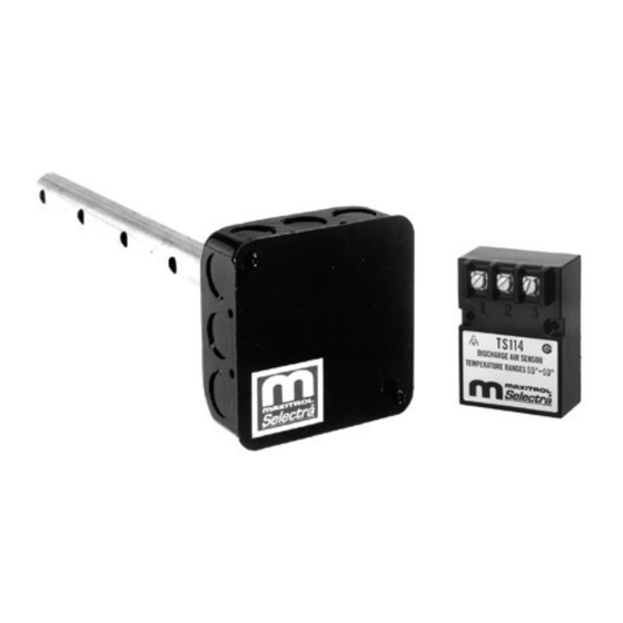
Discharge Air Temperature Sensors: use with Mixing Tube
TS114..........................................................................55° to 90°F
TS114A.....................................................................80° to 130° F
TS114B....................................................................120° to 170° F
TS114C....................................................................160° to 210° F
TS114D..................................................................200° to 250° F
TS114E..................................................................100° to 250° F
TS114F.....................................................................40° to 80° F
TS114G....................................................................90° to 140° F
TS114J.................................110° to 160° F, use w/ AD1014-1116,
TS214__...........................dual sensor - any combination
Example 1 - TS214G....................55° to 90° F and 90° to 140° F,
use w/TD114 & TD114G, or TD214G (selector w/switch).
Example 2 - TS214AD..................80° to 130° F and 200° to 250° F,
use w/TD114A & TD114D, or TD214AD (selector w/ switch).
Mixing Tubes: (and sensor)
Valves
1
of 2 standard ranges available
Lengths:
MT1-9 or 2-9............................9"
MT1-12 or 2-12......................12"
MT1-23 or 2-23......................23"
MT1-28 or 2-28......................28"
MT1-57...................................57"
Pipe Sizes:
M411........................... 3/8" & 1/2"
M511...........................1/2" & 3/4"
M611 ............................3/4" & 1"
MR212D...................1", 1¼", 1½"
MR212E.........................1½" & 2"
MR212G....................... 2½" & 3"
MR212J.......................4" flanged
2 Speed Blower or Dual Fuel
Operation:
MR212D-2................1", 1¼", 1½"
MR212E-2.....................1½" & 2"
MR212G-2.....................2½" & 3"
MR212J-2....................4" flanged
NOTE: M (Modulator) valve requires an
upstream pressure regulator for
low fire & high fire settings. MR
(Modulator/Regulator) valve
requires no upstream pressure
regulator up to 5 psi inlet.
Advertisement
Table of Contents

Summary of Contents for Maxitrol Selectra 14R Series
-
Page 1: Table Of Contents
& high fire settings. MR TD114-1..55° to 90°F w/120° to 170°F (Modulator/Regulator) valve override, use w/TS114 requires no upstream pressure TD114-2...55° to 90°F w/two outputs regulator up to 5 psi inlet. TD114G-2..90° to 140°F w/two outputs © 2013 Maxitrol Company, All Rights Reserved... -
Page 2: System Components
(43) 1.41 2.96 inches (millimeters) (36) (75) 2.25 (57) 3.46 (88) 2.62 3.25 (83) 4.69 (67) (76) (119) (38) 1.75 (44) 0.19 2.56 (4.8) (65) 2.62 (67) Figure 4: T114 Figure 5: TD114 © 2013 Maxitrol Company, All Rights Reserved... -
Page 3: Specifications
Transformer secondary must not be grounded in any portion of wires. Doing so may cause the unit to function erratically or the circuit external to a Maxitrol amplifier. If existing transformer may destroy the amplifier. If shielded wires are used, shield is grounded, a separate, independent transformer must be used. -
Page 4: Wiring Diagrams
© 2013 Maxitrol IMPORTANT: The A1014R integral or remote temperature Figure 11: A1014R Model Amplifier selector’s (TD114) temperature range must match the temperature sensor’s (TS114) temperature range. See page 7 for available integral dial ranges. © 2013 Maxitrol Company, All Rights Reserved... -
Page 5: Valve Adjustments
3. Reconnect the wires to amplifier terminal 4. NOTE: If low fire bypass is on maximum, the desired high fire outlet pressure may not be achieved. © 2013 Maxitrol Figure 14: M411, 511, 611 Valve Adjustments © 2013 Maxitrol Company, All Rights Reserved... - Page 6 © 2013 Maxitrol Company, All Rights Reserved...
-
Page 7: Field Service Checklist
After the troubleshooting test, remove the test resistor and reconnect the Discharge Air Sensor to terminals 3 and 4. If Remote Temperature Selector has been moved or disconnected return it to its original position. © 2013 Maxitrol Company, All Rights Reserved... - Page 8 Maxitrol Company © 2013 Maxitrol Company 23555 Telegraph Rd., PO Box 2230 All Rights Reserved Southfield, MI 48037-2230 SEL14R_MI_EN_09.2013...
Need help?
Do you have a question about the Selectra 14R Series and is the answer not in the manual?
Questions and answers