Advertisement
Quick Links
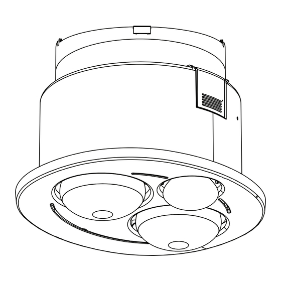
372 mm
Please read carefully: Read through these instructions completely before commencing
installation. Retain for future use.
1
SPECIFICATIONS
Cat. No.
Supply Voltage
Power Input
Fan Motor
Airflow
Ceiling cut-out
Protrusion into ceiling
Required Ceiling Depth
Face protrusion (Excluding Lamps)
Heat Lamps
LED Centre Light
Impeller Diameter
Sound pressure level (dBA) at 3m
Weight (Normal)
* Airflow dependent on installation conditions.
2
PART SUPPLIED
Bathroom heater
Infrared heat lamp (L275HLES)
LED centre lamp (LR80014K)
Wall switch plate (ED770 / 3FLHWE)
Installation instructions / template
3
THINGS TO BE CONSIDERED
Read through these instructions completely before commencing installation.
CAUTION:
This product is not designed to be ducted. If ducting is required then the ducted Instant Heat series,
R622D2 is more suitable for this purpose.
Regulations concerning the discharge of air have to be fulfilled. Local building codes may require
venting to the outside. The volume of the roof space must be a minimum of 3 cubic metres and
adequately ventilated to allow moisture to dissipate. This product is to be installed in standard roof
applications only, not in restricted ceiling cavities as found in multi storey applications (See Fig. 1).
To prevent heat accumulation, adjacent recessed bathroom heaters must be installed at least 1.5
metres apart from each other.
BH2NDWE/BH2NDMS
230-240 V a.c. 50 Hz
600 W
40 W
240 m
/hr max*
3
Ø 300 mm
237 mm
530 mm
20 mm
2 x 275 W
7 W R80 600 lm
Ø 240 mm
44
3.3 kg
1 piece
2 piece
1 piece
1 piece
1 piece
Bathroom Heater 3 in 1
4
INSTALLATION
The infrared lamp heat by direct radiation rather than by heating the air in the room, so the
bathroom heater should be located directly over the drying area. Bathroom heater must not be
installed where there is a possibility of water splashing on to the lamps. Locate in accordance
with the requirements of the Australian/New Zealand Wiring Rules AS/NZS 3000 relating to damp
situations. This means that no part may be located directly above any part of the bath or shower
recess or enclosure. For unenclosed showers refer to Wiring Rules conditions.
Note: Steam will only be removed if there is sufficient flow of air through the room. Ensure
adequate inlets exist through windows, vents or under the door. Airflow path from inlets to
fan should ideally pass over the steam sources.
5
LOCATION
The bathroom heater is for ceiling mounting only, with the lowest point to be at least 2.2 metres
above floor level. It is not intended to be installed in wardrobes or within 300 mm of sides of walls,
as per Fig. 2. There is a danger of combustion if placed too close to curtains or other flammable
materials.
Fig: 1
6
CEILING PREPARATION AND INSTALLATION
Bathroom heater may be installed either between joists using the built in clip fasteners or against
a joist using a screw to replace a clip. Drill a hole in the flange to suit. The clearances between
bathroom heater and adjacent building members shown in Fig . 3 shall be observed. Thermal
insulation or similar material shall not be placed on top of the unit, and adjacent material to the
side shall be kept clear to a minimum distance of 200 mm (Fig. 4). Joists, beams and rafters shall
not be cut or notched to install bathroom heater. After determining the location of bathroom heater
use cut-out template provided to mark out and cut the aperture (Fig. 5). If adequate support is not
available for the bathroom heater, it may be necessary to provide extra strengthening.
300mm
Min.clearance
Unobstructed
Air ow
500mmM in.
2.2M Min.
Fig: 3
7
FIXING TO CEILING
Remove all lamps to prevent damage from clip fasteners. Spin the fan to check for freedom of
rotation. Push the bathroom heater body into the opening allowing the springs to snap open. To
secure, push the lower ends of the springs apart (Fig. 6). Ceiling board thickness should be
adjusted to enable the springs to be fitted without excessive force.
Fig: 5
8
FINAL ASSEMBLY
Check that the power to the unit is off. Position the lamp surround below the unit so that the two
pins on the underside line up with the two holes in the flange. The cover is designed to snap onto
the housing flange (Fig. 7) which sits flush against the ceiling. Insert the three lamps into the
sockets, tightening well to ensure good electrical contact and long life. Wipe the surround and the
bulbs clean. Connect the power and check all functions.
Non Ducted 2 Heat Lamps
Cat. No:
BH2NDWE / BH2NDMS
Instruction Manual
Wall
>300 mm
>300 mm
Fig: 2
>200mm
>200mm
Fig: 4
Fig: 6
Fig: 7
Advertisement

Subscribe to Our Youtube Channel
Related Manuals for LEGRAND HPM BH2NDWE


Summary of Contents for LEGRAND HPM BH2NDWE
- Page 1 Bathroom Heater 3 in 1 Non Ducted 2 Heat Lamps Cat. No: BH2NDWE / BH2NDMS Instruction Manual INSTALLATION The infrared lamp heat by direct radiation rather than by heating the air in the room, so the bathroom heater should be located directly over the drying area. Bathroom heater must not be installed where there is a possibility of water splashing on to the lamps.
- Page 2 ● Legrand warrants this product for a period of 5 years from the date of purchase. Our goods (which we refer to in the Warranty as the Products) come with guarantees that cannot be excluded under the Australian and New Zealand Consumer Laws.
Need help?
Do you have a question about the HPM BH2NDWE and is the answer not in the manual?
Questions and answers