Table of Contents
Advertisement
Quick Links
Advertisement
Table of Contents

Summary of Contents for Taisync ViuRC5
- Page 1 Taisync ViuRC5 User Manual www.taisync.com...
-
Page 2: Table Of Contents
Contents 1 Package Contents ............................1 2 Product Description ..........................2 2.1 Parameters ..........................2 2.2 RC Controls ..........................3 2.3 Remote Controller Interfaces ..................... 5 2.4 Air Unit Interfaces ........................5 2.5 Status Indicators ......................... 6 3 Connections ............................8 4 Before Use ............................10 4.1 Remote Controller Operation ....................10 4.2 Antenna Installation ........................11 5 Device Management ..........................13... -
Page 3: Package Contents
1 Package Contents Remote Controller & Air Unit Accessories Item Quantity Charger USB cable Air unit adaption cable Air unit antenna Ethernet cable Power cable Air unit IP camera... -
Page 4: Product Description
2 Product Description 2.1 Parameters General information Working frequency 2.4GHz/5GHz Transmitting power 26dBm@2.4GHz, 24dBm@5GHz Max. range 15km Arg. range RC channels Operational temperature -10℃~ +55℃ Air unit Dimension 83*50*22.5mm Weight Voltage input 6S~16S(22.2V-59.2V) Power consumption Interface ETH*2, TTL*2, S.BUS*1 Remote controller Display 5.5’’... -
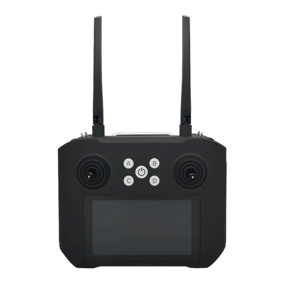
Page 5: Rc Controls
2.2 RC Controls Antenn Power Button Switch Switch Dial Dial Stick Stick Button Button Touchscreen Battery Indicator... - Page 6 Channel Name Channel assignment Note Right stick Right stick Left stick Left stick Left upper 3-point switch Left lower 3-point switch Right upper 3-point switch Right lower 3-point switch Left dial Left dial Self-locking by Button A default Self-locking by Button B default Non-self-locking...
-
Page 7: Remote Controller Interfaces
2.3 Remote Controller Interfaces Power Debug 2.4 Air Unit Interfaces... -
Page 8: Status Indicators
2.5 Status Indicators 2.5.1 RC status light indicators Power indicator Battery level indicator (1)Power indicator It will be solid on in red after RC is powered on. (2)Battery level indicator Battery level indication 0%—25% ● ○ ○ ○ 25%—50% ● ●... - Page 9 2.5.2 Air unit status indicator& button Bind status indicator Bind button The 2 LED lights of air unit are used to indicate the bind status only, when air unit is in binding, they will be flashing in yellow/green respectively. Note: Unit is bound already before factory delivery, user do not need to do bind again after unfolding the box.
-
Page 10: Connections
3 Connections Here take the Pixhawk 4 as an example: XT60 connector, voltage input 6S~16S Antennas... - Page 11 (1) Telemetry connection: Telemetry connection settings have been hard-coded in the pre-installed QGC, user do not need to set anymore in the remote controller, but make sure baud rate of flight controller is 115200, and the used telemetry port of air unit is TTL1. (2)...
-
Page 12: Before Use
4 Before Use 4.1 Remote Controller Operation 4.1.1 RC power on/off (1)Power on Press the power button to start the power system, then press-and-hold the power button till it beeps. Power button Battery level indicator... -
Page 13: Antenna Installation
(2)Power off Press-and-hold the power button till the “Power off” popped up on screen, tap on it to power off the remote controller. Press-and-hold the button combination of Power and C for 15 seconds, remote controller will be shut down forcibly. (3)Sleep Press the power button to get the screen into sleep when the remote controller is powered on, and invoke by it also. - Page 14 (1)Keep the antennas vertical to the ground; (2)Keep the antennas in parallel, do not cross or overlap with each other. 4.2.2 Air unit antennas (1)The two RF cables used between air unit’s RF ports and antennas should not be crossed with each other, antenna, RF cable and SMA connector should not be directly contacted to metal, carbon fiber parts;...
-
Page 15: Device Management
5 Device Management 5.1 RC Settings 5.1.1 Stick calibration Stick correction can be performed periodically to ensure the accuracy of stick channel outputs. Stick calibration method (1)Before start, please make sure both sticks stand still without position offset caused by external... - Page 16 force. (2)Select “Stick ” and access the setup screen shown below by touching “Start”. (3)If the sticks are at the neutral position already, but the blue dots are not at the central, it means the stick neutral position has an offset.Now do not move the stick, touch on “Next” to do neutral position calibration.
-
Page 17: Channel Settings
5.1.2 Channel settings Servo travel end point, operation direction reversal and channel mapping can be set by user via channel settings. Servo travel end point Default servo travel end point ranges 200~1800. User can also change the end point manually. Select the channel, and input the value. - Page 18 Channel mapping ViuRC5 has 14 channels in total, and allow user to define the mapping relations between logical communication channel and physical channel(button, switch, stick, etc.). Select the channel and touch on the channel name to bring up the configuration window.
-
Page 19: Volume Calibration
5.1.3 Volume calibration Volume correction can be performed periodically to ensure the output accuracy of volume channel. Neutral position and end point can be calibrated. Volume calibration method (1)Before start, please make sure both sticks stand still without position offset caused by external force. - Page 20 (3)If the volumes stand still already, but the output value is not 0, it means the volume neutral position has an offset.Now do not move the volume, touch on “Next” to do neutral position calibration. (4)Go on with end point calibration. According to the prompt, move volume fully in each direction, afterwards, touch on “Complete”...
-
Page 21: System Settings
5.1.4 System settings Button mode setting, stick mode setting and restore factory settings can be made at system page. Button setting There are options of self-locking and non-self-locking for the buttons of A, B, C and D. Self-locking for button A and button B, non-self-locking for button C and button D by default, user can change it manually. -
Page 22: Transceiver
after user press again, the output will be back to 200. Non-self-locking: when press-and-hold the button, the output of this channel will be 1800, as soon as user release the button, the output goes back to 200. Stick setting There are options of American, Japanese, Chinese and custom for stick mode. 5.2 Transceiver There is radio transmitter and receiver integrated in the remote control system. - Page 23 Parameter settings At Set page, user can do binding operation, working frequency mode change, and restore factory settings. When working mode is Auto, system will work at the least interfered frequency channel dynamically, when it is Manual, user can manually select the specific frequency to use. Note: (1)Baud rate of serial telemetry is hard-coded as 115200 in pre-installed QGC, so baud rate of the radio link should keep aligned if pre-installed QGC is used.
- Page 24 reference. The TFTP server is used for air unit remote firmware upgrade, IP address of air unit(192.168.199.18) is set here as the TFTP server IP address. If air unit IP address is changed, the server IP address must be modified accordingly.
-
Page 25: Upgrade
5.4 Upgrade Check for firmware updates of remote controller, transceiver, and app tool. Touch on “Run” to do the firmware version check, results will be listed. If it’s not the latest, upgrade can be done online over the Internet access. -
Page 26: Version
5.5 Version Check for the detailed hardware device type and software version. 6 Notice (1) Check battery level is enough for the whole flight before take off; (2) Make sure antennas are properly installed to avoid drone body blockage and do not power on device without antenna installation;... -
Page 27: Faq
7 FAQ (1) Telemetry connection failure? A: Check baud rate of FC, radio link and QGC are the same or not, check telemetry cable connection between air unit and FC, check FC telemetry signal is TTL or not. (2) Is it possible to install other app in RC? A: it can.
Need help?
Do you have a question about the ViuRC5 and is the answer not in the manual?
Questions and answers
"I am using the same transmitter, but I have tried many times to connect via Wi-Fi and Bluetooth. I also tried connecting to Mission Planner GCS, but it’s not connecting. Are there any options available to connect the laptop GCS using Wi-Fi or Bluetooth?