
Summary of Contents for Rohde & Schwarz ESCU Series
- Page 1 ® R&S ESCU Pre-amplifier for Emission Measurement User Manual (Æ2Þ62) 5602800602 Version 02...
- Page 2 ® This manual applies to the following R&S ESCU models and its options: ● R&S ESCU08-20, 0.1 GHz to 8 GHz, 33 dB min. gain, DC Jack (order no.: 5602.9825.20) ● R&S ESCU08-21, 0.1 GHz to 8 GHz, 31 dB min. gain, R&S ESCU-Z01 (order no.: 5602.9825.21) ●...
-
Page 3: Table Of Contents
® Contents R&S ESCU Contents 1 Safety and regulatory information........5 1.1 Safety instructions................5 1.2 Labels on the product................9 1.3 Warning messages in the documentation.......... 9 1.4 Korea certification class B..............9 2 Documentation overview............ 11 2.1 This manual..................11 2.2 Related manuals..................11 2.3 Specifications and brochures............12 2.4 Calibration certificate................. - Page 4 ® Contents R&S ESCU 5 Troubleshooting..............28 5.1 Preamplifier without a bias unit............28 5.2 Preamplifier with a bias unit.............. 28 5.3 Contacting customer support............29 6 Calibration................31 7 Maintenance and lifecycle..........32 7.1 Cleaning....................32 7.2 Storage....................32 7.3 Transporting..................32 7.4 Disposal....................33 Index..................
-
Page 5: Safety And Regulatory Information
® Safety and regulatory information R&S ESCU Safety instructions Safety and regulatory information The product documentation helps you use the product safely and efficiently. Fol- low the instructions provided here and in the following chapters. Intended use The R&S ESCU is intended for improving the signal to noise floor margin in EMC testing of electronic components and devices in industrial, administrative, and lab- oratory environments. - Page 6 ® Safety and regulatory information R&S ESCU Safety instructions Use the product only for its intended use and within its performance limits. Inten- ded use and limits are described in the product documentation such as the speci- fications document, manuals and the printed "Safety Instructions" document. If you are unsure about the appropriate use, contact Rohde &...
- Page 7 ® Safety and regulatory information R&S ESCU Safety instructions Setting up the product Always place the product on a stable, flat and level surface with the bottom of the product facing down. If the product is designed for different positions, secure the product so that it cannot fall over.
- Page 8 ® Safety and regulatory information R&S ESCU Safety instructions ● Only use intact cables and route them carefully so that they cannot be dam- aged. Check the power cables regularly to ensure that they are undamaged. Also ensure that nobody can trip over loose cables. ●...
-
Page 9: Labels On The Product
® Safety and regulatory information R&S ESCU Korea certification class B Labels on the product Labels on the casing inform about: ● Personal safety, see "Meaning of safety labels" on page 8 ● Product and environment safety, see Table 1-1 Table 1-1: Labels regarding product and environment safety Labeling in line with EN 50419 for disposal of electrical and electronic equipment after the product has come to the end of its service life. - Page 10 ® Safety and regulatory information R&S ESCU Korea certification class B 이 기기는 가정용(B급) 전자파 적합기기로서 주로 가정에서 사용하는 것을 목적으 로 하며, 모든 지역에서 사용할 수 있습니다. User Manual 5602.8006.02 ─ 02...
-
Page 11: Documentation Overview
® Documentation overview R&S ESCU Related manuals Documentation overview The following documents are relevant when using the R&S ESCU preamplifier. Unless specified otherwise, you find the documents at: www.rohde-schwarz.com/manual/escu This manual Describes the steps from delivery to installation of the accessory. A printed ver- sion is delivered with the R&S ESCU. -
Page 12: Specifications And Brochures
® Documentation overview R&S ESCU Calibration certificate Specifications and brochures The specifications document, also called data sheet, and brochure contain an overview of the R&S ESCU preamplifiers and its technical specifications. See www.rohde-schwarz.com/brochure-datasheet/escu. Calibration certificate The document is available on https://gloris.rohde-schwarz.com/calcert. You need the device ID of your product, which you can find on a label on the side panel. -
Page 13: Preparing For Use
® Preparing for use R&S ESCU Choosing the operating site Preparing for use Here, you can find basic information about setting up the product for the first time. Lifting and carrying For safety information, see "Lifting and carrying the product" on page 6. -
Page 14: Setting Up The Product
® Preparing for use R&S ESCU Setting up the product Electromagnetic compatibility classes The electromagnetic compatibility (EMC) class indicates where you can operate the product. The EMC class of the product is given in the specifications docu- ment. ● Class B equipment is suitable for use in: –... - Page 15 ® Preparing for use R&S ESCU Setting up the product Each antenna uses different types of brackets. Use only the appropriate bracket. If ordered, the brackets for the respective antennas are included in the delivery in a separate packaging. The list of compatible antennas includes: ●...
- Page 16 ® Preparing for use R&S ESCU Setting up the product Double-ridged waveguide horn antenna 3117 Figure 3-2: Installing a preamplifier onto an antenna 3117 = Installing the preamplifier onto a bracket for antenna 3117 (order no.: 5602.9777.00) = Bottom view of the bracket 1a and 1b = Bracket for antenna 3117 (side and bottom view) 2a and 2b = Preamplifier (side and bottom view) 3a and 3b = DIN7985 M3x6 screw (side and bottom view)
-
Page 17: Considerations For Test Setup
® Preparing for use R&S ESCU Considerations for test setup BBHA 9120 E double-ridged broadband horn antenna Figure 3-4: Installing a preamplifier onto a BBHA 9120 E antenna = Installing the preamplifier onto a bracket for BBHA 9120 E antenna (order no.: 5602.9790.00) = Bottom view of the bracket 1a and 1b = Preamplifier (side and bottom view) -
Page 18: Connecting To Power
® Preparing for use R&S ESCU Connecting to power Signal input levels The maximum input signal level is +15 dBm. Keep the signal levels within the specified range to avoid damage to the product and connected devices. See also Chapter 3.7, "Connecting to an RF source", on page 19. -
Page 19: Connecting To An Rf Source
® Preparing for use R&S ESCU Connecting to an RF source 2. NOTICE! Risk of damaging the product. Leaving the devices dangling in mid- air using cables can break the connectors or the cable. Install the devices only on a flat surface. Plug the AC power cable into a power outlet with ground contact. - Page 20 ® Preparing for use R&S ESCU Connecting to an RF source To connect the preamplifier to an RF source Prerequisite: You provide an RF cable with at least one 2.92 mm K type male connector. The product is securely fixed on a flat surface. 1.
-
Page 21: Connecting To Other Devices
® Preparing for use R&S ESCU Connecting to other devices See also Table 5-1. 3. Using a torque wrench, loosen the RF connectors in the setup (Figure 3-6). 4. Disconnect the cables. Connecting to other devices The test setup for using the preamplifier with or without a bias unit differs. To complete the setup without a bias unit Prerequisite: You provide an RF cable with at least one N-type male connector. - Page 22 ® Preparing for use R&S ESCU Connecting to other devices Connect the RF cable to the [RF Out] female 2.92 mm K type connector of the bias unit (2 in Figure 3-7). If the connector type of the RF cable is different, use an appropriate adapter. Figure 3-7: Preamplifier setup with a bias unit = Measuring device, such as a spectrum analyzer 2 and 7 = RF cable with a 2.92 mm male connector at one end (not included in the delivery)
-
Page 23: Switching On Or Off
® Preparing for use R&S ESCU Switching on or off To disconnect the test setup 1. Press the preamplifier's pushbutton to switch it off. The LED on the pushbutton is off. If a bias unit is available, the [STATUS] LED indicator turns amber. See also Table 5-1. - Page 24 ® Preparing for use R&S ESCU Switching on or off To switch off the product Prerequisite: The preamplifier and the bias unit, if available, are powered and switched on. 1. Push the pushbutton on the preamplifier. The pushbutton on the preamplifier is latched off and the LED indicator on the pushbutton turns off.
-
Page 25: About R&S Escu
® About R&S ESCU R&S ESCU Preamplifier About R&S ESCU The R&S ESCU preamplifier is designed to boost an incoming weak signal and improve the sensitivity of the receiver system. It also improves the signal-to-noise floor margins. There are various models available for different frequency ranges. These models have similar installation procedures but different specifications. -
Page 26: Bias Unit
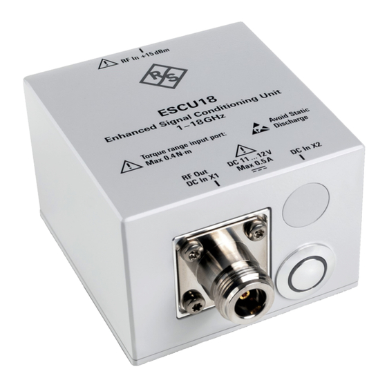
® About R&S ESCU R&S ESCU Bias unit [RF Out/DC In X1] An N type female RF output connector to connect to devices such as a spectrum analyzer. See Chapter 3.8, "Connecting to other devices", on page 21. When used with a bias unit, this connector receives DC voltage from the bias unit. [DC In X2] A 12 V DC input voltage connector. - Page 27 ® About R&S ESCU R&S ESCU Bias unit "[RF Out]" on page 27 RF output connector (not shown) "[DC In]" on page 27 input voltage connector (not shown) 3 = R&S ESCU-Z01 bias unit "Ground" on page 27 connector 5 = On/off "Pushbutton"...
-
Page 28: Troubleshooting
® Troubleshooting R&S ESCU Preamplifier with a bias unit Troubleshooting If the preamplifier or the bias unit is not functioning normally, switch it off then on using its pushbutton. For details on the possible fault conditions, see: ● Chapter 5.1, "Preamplifier without a bias unit", on page 28 ●... -
Page 29: Contacting Customer Support
® Troubleshooting R&S ESCU Contacting customer support Table 5-1: LED indicators and the status of the devices LED indicators Devices conditions On the bias unit On the pre- amplifier Pushbutton [FAULT] [STATUS] Pushbutton Unlit Unlit Unlit Unlit The bias unit and preamplifier are switched off and are in the off state. - Page 30 ® Troubleshooting R&S ESCU Contacting customer support Contact information Contact our customer support center at www.rohde-schwarz.com/support, or fol- low this QR code: Figure 5-2: QR code to the Rohde & Schwarz support page User Manual 5602.8006.02 ─ 02...
-
Page 31: Calibration
® Calibration R&S ESCU Calibration The R&S ESCU preamplifier is typically used inside a chamber. We recommend that you calibrate the preamplifier and bias unit, if available, with the actual test setup to ensure an accurate overall correction factor of the signal path. Perform the calibration at the ambient temperature specified in the specifications. -
Page 32: Maintenance And Lifecycle
® Maintenance and lifecycle R&S ESCU Transporting Maintenance and lifecycle The product does not require regular maintenance. It only requires occasional cleaning. It is however advisable to check the nominal data from time to time. ● Cleaning......................32 ● Storage......................32 ●... -
Page 33: Disposal
® Maintenance and lifecycle R&S ESCU Disposal Packing Use the original packaging material. It consists of antistatic wrap for electrostatic protection and packing material designed for the product. If you do not have the original packaging, use similar materials that provide the same level of protection. -
Page 34: Index
® Index R&S ESCU Index About ............25 Fault indicator Bias unit ..........25 Bias unit ..........27 Preamplifier .........25 Ground Bias unit Connector ........... 27 DC input voltage ......... 27 DC input voltage to preamplifier ..27 Fault indicator ........27 How to Pushbutton ..........27 Connecting to other devices .... - Page 35 ® Index R&S ESCU Pushbutton Bias unit ..........27 Preamplifier .........26 RF connection Connecting the product .......19 RF output Connecting ........26, 27 RF source Connecting ..........26 Safety instructions ....... 5, 11 Setting up the product Installing on an antenna ......14 Operating site ........
Need help?
Do you have a question about the ESCU Series and is the answer not in the manual?
Questions and answers