Advertisement
Quick Links
®
HOW TO USE AND MAINTAIN
YOUR
®
®
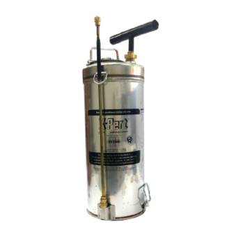
HUDSON
X-PERT
SPRAYER
DISEASE VECTOR CONTROL SPRAYERS
INSTRUCTION PART #: 723-504
Please read and save these instructions. Read carefully before
attempting to assemble, install, operate or maintain the
product described.
Protect yourself and others by observing all safety information.
Failure to comply with instructions could result in personal
injury and/or property damage! Retain instructions for future
reference.
REMINDER: Keep your dated proof of purchase for warranty
purposes! Attach it to this manual or file it for safekeeping.
1
MODEL #: 871-596B
Advertisement

Related Manuals for Hudson X-PERT 67322AD


Summary of Contents for Hudson X-PERT 67322AD
- Page 1 ® HOW TO USE AND MAINTAIN YOUR ® ® HUDSON X-PERT SPRAYER DISEASE VECTOR CONTROL SPRAYERS INSTRUCTION PART #: 723-504 Please read and save these instructions. Read carefully before attempting to assemble, install, operate or maintain the product described. Protect yourself and others by observing all safety information.
- Page 2 SERIOUS INJURY personal or environmental contamination. your Hudson® X-Pert® sprayer to apply Do not use caustic (alkalis) or corrosive (acids) materials, bleach, or ammonia. Many of these materials can produce a violent chemical reaction with the sprayer, can corrode metal parts, or weaken hose, gaskets, or other components.
-
Page 3: California Proposition
ALWAYS KEEP SPRAYER AND SPRAY MATERIALS OUT OF REACH OF CHILDREN. IMPORTANT! Use only appropriate and genuine Hudson® replacement parts. Improper or after-market parts may not fit correctly and/or may be weakened by spray chemicals and fail under pressure, resulting in SERIOUS INJURY from forcible ejection of parts or high-pressure discharge of spray material. - Page 4 PREPARING YOUR HUDSON® X-PERT® SPRAYER Step 1. Identify and collect Hudson® X-Pert® sprayer you are planning to use. If this is a sprayer you will eventually use, identify the sprayer or mark in a way so you can recognize it when you get to your spray destination.
- Page 5 Pump Assembly See page 13 for service parts. Hose & Valve Assembly See page 14 for service parts. Extension Assembly See page 15 for service parts. Tank Assembly See pages 13-14 for service parts. Step 5. Attach the carrying strap to the upper and lower attachments on the sprayer by clipping both ends of the strap to the “D rings”...
- Page 6 Step 6. Insert the cylinder pump into the sprayer through the pump opening. Rotate it so that the flat portion at the upper portion of the cylinder (see Fig. 2) is against the inside surface of the sprayer. NOTE: it is important that this is done correctly to ensure proper installation.
- Page 7 GO TO Step 13. Step 13. Carefully tighten the pump cap, hose connector, and lance connector using a wrench or pliers (spanners). Do not over tighten. GO TO Step 14. Congratulations! Your Hudson® X-Pert® sprayer is fully assembled and ready!
- Page 8 Operating the Hudson® X-Pert® Sprayer Step 14. Inspect the sprayer to make sure all parts are installed correctly. GO TO Step 15. Step 15. Sprayer has green pressure release valve. GO TO Step 16. Sprayer has brass pressure release valve. GO TO Step 17.
- Page 9 Step 23. Close sprayer. Insert the cover in the sprayer. Hold it vertically while inserting it in the sprayer making sure the handle is parallel to the body of the cover. GO TO Step 23.1. 23.1. Once inside, rotate it until it is horizontal and parallel to the internal surface of the body of the sprayer.
- Page 10 Step 28. Grab the sprayer by the strap. Slowly raise the strap until all the slack is taken off. Do not attempt to lift or carry the sprayer by the cover handle or any other component. They are not designed for this purpose and may be damaged or broken. Lift the sprayer by the strap and place the strap on your shoulder.
- Page 11 Step 35. Aim the lance at the spot you want Fig. 12 to spray. Make sure you maintain the required distance from the nozzle to the surface to be sprayed. Squeeze the trigger handle. See Fig. 12. Continue to spray as explained during the training session.
- Page 12 Storing the Sprayer for Extended Period Step 39. After going through the Progressive Rinse Method, disassemble the sprayer. Components should be kept in covered, properly labeled storage containers in a secure location. All parts should be clean and dry before storing for a period of weeks or months.
- Page 13 PUMP AND CYLINDER SERVICE PARTS Ref. Part Number Description 147-541 Plunger Assembly, complete for 3 & 3.5 gallon unit 147-537 Plunger Assembly, complete for 2 gallon (8L) unit 147-501 Plunger Tube and Handle, only for 3 & 3.5 gallon unit 147-504 Plunger Tube and Handle, only for 2 gallon unit 151-028...
- Page 14 DISCHARGE ASSEMBLY SERVICE PARTS LIST Ref. Part Number Description 149-706 Shutoff Assembly, complete, Thrustless™ 149-702 Valve Body Cap, with O-Ring gaskets 115-733 Shutoff Valve Body Cap 805-335 Valve Body Cap O-Ring, for valve pin 805-309 Valve Body Cap O-Ring 115-726 Shutoff Valve Pin 110-243 Teflon Valve Pin Spacer...
- Page 15 EXTENSION TUBE AND NOZZLE SERVICE PARTS NOZZLE FLOW 64 63 65 REGULATOR ASSEMBLY Ref. Part Number Description 141-966 Extension Tube and Nozzle Assembly 141-968 Extension Tube and Nozzle Flow Regulator Assembly for 67362 & 67462 141-967 Extension Tube Assembly Only 805-337 O-Ring Gasket for Extension Tube 141-989...
- Page 17 673-001 Filter for Filler Opening...
- Page 18 MODEL COMPONENT BREAKDOWN 11.3 Liter 13.2 Liter Pressure Shutoff Nozzle Flow Thrustless Strap (3.0 Gallons) (3.5 Gallons) Gauge Cock Regulator Shutoff 50 mm (2 in.) 67322AD 67422AD 67322WD 67422WD 67362AD 67462AD 67362WD 67462WD...
- Page 19 SYMBOLS EMBOSSED ON TANK INDICATING YEAR OF MANUFACTURING...
- Page 20 Sign of the Best Buy H.D. Hudson Manufacturing Company 1000 Foreman Rd Lowell, MI 49331 USA Phone: 312.644.2830 Fax 312.644.7989 www.hdhudson.com international@hdhudson.com...
Need help?
Do you have a question about the X-PERT 67322AD and is the answer not in the manual?
Questions and answers
Здравствуйте сколько стоит доставка